307-525

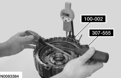
100-002 (TOOL-4201-C) or equivalent

307-555
SECTION 307-01: Automatic Transaxle/Transmission — 6R80
| 2014 Mustang Workshop Manual
|
DISASSEMBLY AND ASSEMBLY OF SUBASSEMBLIES
| Procedure revision date: 01/07/2013
|
| Compressor, Clutch Spring
307-525 |
| Dial Indicator Gauge with Holding Fixture
100-002 (TOOL-4201-C) or equivalent |
| End Play Gauge, Clutch
307-555 |
| Item | Specification |
|---|---|
| Motorcraft® MERCON® LV Automatic Transmission Fluid
XT-10-QLVC (US); CXT-10-LV12 (Canada) | MERCON® LV |
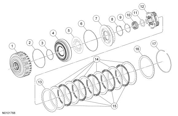
| Item | Part Number | Description |
|---|---|---|
| 1 | 7A360 | Forward clutch drum |
| 2 | 7A548 | Forward clutch piston outer O-ring seal |
| 3 | 7A548 | Forward clutch piston inner O-ring seal |
| 4 | 7A262 | Forward clutch piston |
| 5 | 7A480 | Forward clutch piston return spring |
| 6 | 7A548 | Forward clutch balance dam O-ring seal |
| 7 | 7H360 | Forward clutch balance dam |
| 8 | 7H365 | Forward clutch balance dam retaining ring |
| 9 | 7H579 | Sun gear retaining ring |
| 10 | 7D063 | Sun gear |
| 11 | 7H375 | Bearing (T1) |
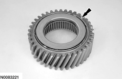
| 12 | 7A398 | Planetary gear |
| 13 | 7E085 | Forward clutch cushion spring |
| 14 | 7E314 | Forward clutch external splined steel plates (quantity model dependent) |
| 15 | 7B164 | Forward clutch internal splined friction plates (quantity model dependent) |
| 16 | 7B066 | Forward clutch pressure plate |
| 17 | 7D483 | Forward clutch plate retaining ring |
Disassembly
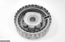
NOTE: Inspect the forward clutch drum and the friction and steel plates for damage. Install new components as necessary.
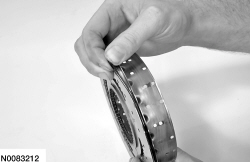
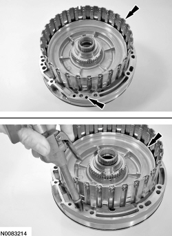
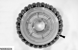
Remove and inspect the forward clutch steel and friction plates.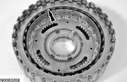
NOTE: The bottom of the Clutch Spring Compressor will need to be installed from the back side of the forward clutch assembly.
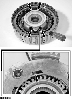
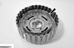
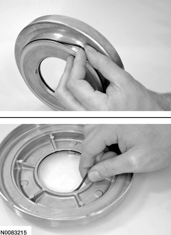
Using the Clutch Spring Compressor, slightly collapse the balance dam to gain access to the retaining ring and remove the retaining ring.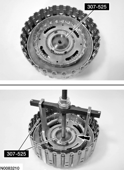
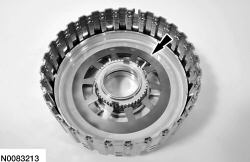
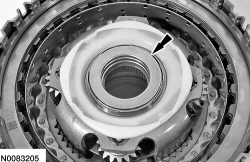
NOTE: The T1 thrust bearing may have stuck to the sun gear when it was removed.
Remove the T1 bearing from the planetary carrier.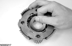
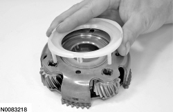
Assembly
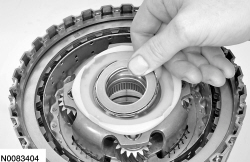
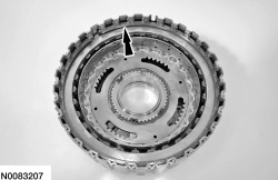
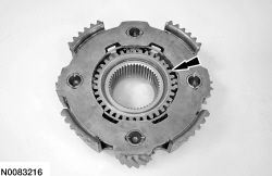
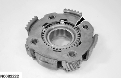
NOTE: If a new planetary assembly is being installed, the new planetary assembly may not come with the snap ring installed.
Install the planetary assembly snap ring, if necessary.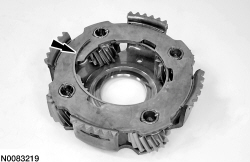
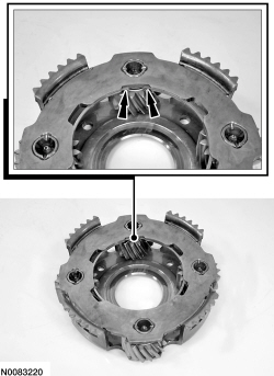
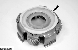
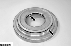
NOTE: Prior to releasing the Clutch Spring Compressor, make sure that the snap ring is fully seated.
Using the Clutch Spring Compressor, slightly collapse the balance dam to install the retaining ring. Install the retaining ring.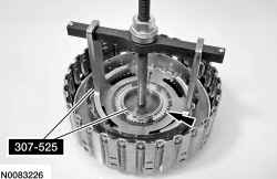
NOTE: Friction and steel plate quantity will vary based on engine displacement. For additional information, refer to the Clutch Plate Quantity chart in the Specifications portion of this section.
Soak the new forward clutch plates in clean transmission fluid.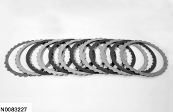
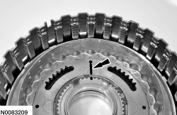
NOTE: All forward clutch plates, friction and steel are of a wave-type design.
Install the forward clutch assembly into the Clutch End Play Gauge and install the Dial Indicator Gauge with Holding Fixture and position the plunger so it fits into the opening of the snap ring.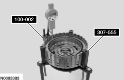
| Description | Reading |
|---|---|
| Reading A | |
| Reading B | |
| Add reading A to reading B for a total end clearance | |
| Divide the total reading by 2 for an average end clearance |
NOTE: If the final measurement is not within specification, install a new snap ring until the correct specification is achieved.