
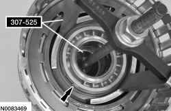
307-525

100-002 (TOOL-4201-C) or equivalent

307-555
SECTION 307-01: Automatic Transaxle/Transmission — 6R80
| 2014 Mustang Workshop Manual
|
DISASSEMBLY AND ASSEMBLY OF SUBASSEMBLIES
| Procedure revision date: 01/07/2013
|
| Compressor, Clutch Spring
307-525 |
| Dial Indicator Gauge with Holding Fixture
100-002 (TOOL-4201-C) or equivalent |
| End Play Gauge, Clutch
307-555 |
| Item | Specification |
|---|---|
| Motorcraft® MERCON® LV Automatic Transmission Fluid
XT-10-QLVC (US); CXT-10-LV12 (Canada) | MERCON® LV |
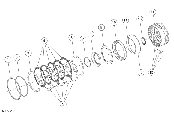
| Item | Part Number | Description |
|---|---|---|
| 1 | 7D483 | Center support retaining ring |
| 2 | 7D483 | Intermediate clutch pack retaining ring |
| 3 | 7B066 | Intermediate clutch pressure plate |
| 4 | 7B164 | Intermediate clutch internal splined friction plates (quantity model dependent) |
| 5 | 7B442 | Intermediate clutch external splined steel plates (quantity model dependent) |
| 6 | 7E085 | Intermediate clutch cushion spring |
| 7 | 7A577 | Intermediate clutch snap ring |
| 8 | 7B043 | Intermediate clutch return spring retaining ring |
| 9 | 7A480 | Intermediate clutch piston return spring |
| 10 | 7E005 | Intermediate clutch piston (model dependant) |
| 11 | 7F225 | Intermediate clutch piston inner seal |
| 12 | 7F224 | Intermediate clutch piston outer seal |
| 13 | 7F373 | Bearing (T6) |
| 14 | 7A130 | Intermediate/low/reverse clutch center support |
| 15 | 7G199 | Center support seals (2 — 7G199, 1 — 7G087, 1 — 7G484) |
Disassembly
NOTICE: The intermediate clutch plate quantity is model dependent on engine size. Check the clutch plate quantity charts in specifications for the correct clutch plate quantity. Failure to install the correct clutch plate quantity will result in transmission failure.
NOTICE: The intermediate clutch piston is model dependent on engine size due to the different quantity of intermediate clutch plates. If installing a new intermediate clutch piston, check to make sure the height of the new piston is the same as the original piston. Failure to install the correct piston will result in transmission failure.
Assembly
NOTE: Friction and steel plate quantity will vary based on engine displacement. For additional information, refer to the Clutch Plate Quantity Chart in the Specifications portion of this section.
Soak the new intermediate clutch plates in clean automatic transmission fluid.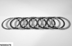
NOTE: All intermediate clutch plates, friction and steel are of a wave-type design.
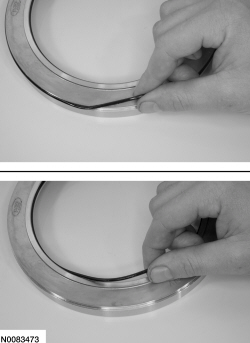
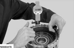
Install the intermediate clutch assembly into the Clutch End Play Gauge and install the Dial Indicator Gauge with Holding Fixture and position the plunger so it fits into the opening of the snap ring.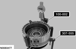
| Description | Reading |
|---|---|
| Reading A | |
| Reading B | |
| Add reading A to reading B for a total end clearance | |
| Divide the total reading by 2 for an average end clearance |
NOTE: If the final measurement is not within specification, install a new snap ring until the correct specification is achieved.