
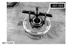
307-525

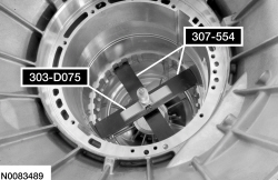
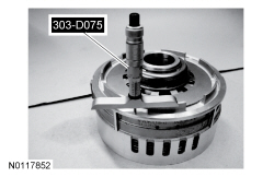
303-D075 (D92P-4201-A) or equivalent

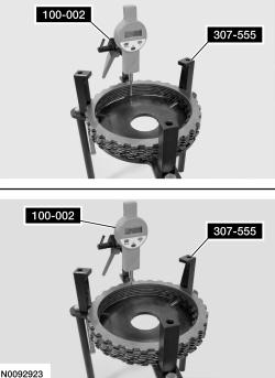
100-002 (TOOL-4201-C) or equivalent

307-555

307-554
SECTION 307-01: Automatic Transaxle/Transmission — 6R80
| 2014 Mustang Workshop Manual
|
DISASSEMBLY AND ASSEMBLY OF SUBASSEMBLIES
| Procedure revision date: 01/07/2013
|
| Compressor, Clutch Spring
307-525 |
| Depth Micrometer
303-D075 (D92P-4201-A) or equivalent |
| Dial Indicator Gauge with Holding Fixture
100-002 (TOOL-4201-C) or equivalent |
| End Play Gauge, Clutch
307-555 |
| Gauge, D-Clutch Measurement
307-554 |
| Item | Specification |
|---|---|
| Motorcraft® MERCON® LV Automatic Transmission Fluid
XT-10-QLVC (US); CXT-10-LV12 (Canada) | MERCON® LV |
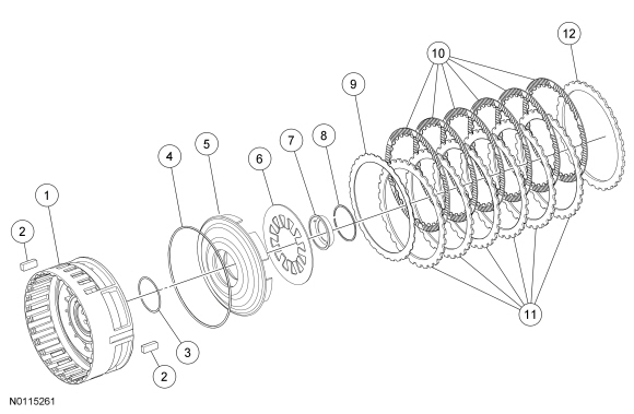
| Item | Part Number | Description |
|---|---|---|
| 1 | 7A130 | Intermediate/low/reverse clutch center support |
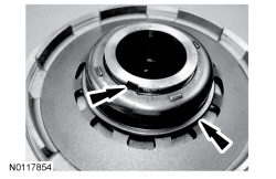
| 2 | 7B220 | Center support keys (2 required) |
| 3 | 7F225 | Low/reverse clutch piston center seal |
| 4 | 7D403 | Low/reverse clutch cylinder outer seal |
| 5 | 7A262 | Low/reverse clutch piston |
| 6 | 7B070 | Low/reverse clutch return spring |
| 7 | 7H318 | Low/reverse clutch return spring retainer |
| 8 | 7D483 | Low/reverse clutch return spring snap ring |
| 9 | 7E085 | Low/reverse clutch cushion spring |
| 10 | 7B164 | Low/reverse clutch internal splined friction plates (internally splined to the rear planetary carrier) |
| 11 | 7B442 | Low/reverse clutch external splined steel plates (externally splined to the case) |
| 12 | 7B066 | Low/reverse clutch pressure plate (externally splined to the case) (select fit) |
Disassembly
NOTICE: The low/reverse clutch plate quantity is model dependent on engine size. Check the clutch plate quantity charts in specifications for the correct clutch plate quantity. Failure to install the correct clutch plate quantity will result in transmission failure.
NOTE: The low/reverse clutch plates are installed in the case during the transmission assembly procedure.
Assembly
Low/reverse piston
Low/reverse clutch stackup
NOTE: All low/reverse clutch plates, friction and steel are of a wave-type design.
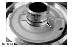
Install the D-Clutch Measurement Gauge into the case.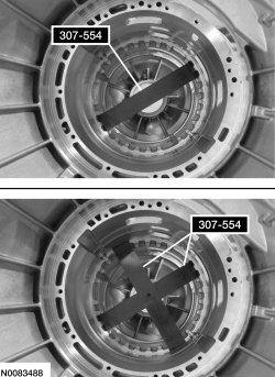
| Description | Reading |
|---|---|
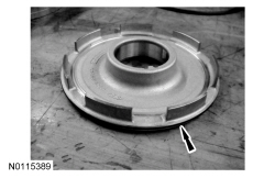
| Measure the distance from the top of the upper gauge bar to the top of the lower gauge bar. Record this reading as the case measurement. Record as reading A. |
| Description | Reading | |
|---|---|---|
| A. | Place the low/reverse clutch pack on the Clutch End Play Gauge with the wave spring down and the pressure plate on top. Using the Dial Indicator Gauge with Holding Fixture, place the plunger on the pressure plate. Slide the clutch to the side so the plunger of the Dial Indicator is touching the gauge plate of the Clutch End Play Gauge. Zero out the Dial Indicator Gauge. | |
| B. | Carefully lift the plunger enough to slide the clutch pack under the plunger to take a reading. Record this reading. Rotate the clutch pack 180 degrees and take a second reading. Add the first and second readings together and divide the total by 2. Record this reading as B. |
| Description | Reading |
|---|---|
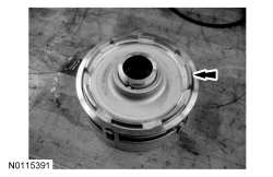
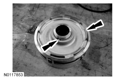
| Measure the piston to center support shoulder height. Record this measurement. Rotate the center support 180 degrees and record this measurement. Add the first and the second measurements, then divide by 2. Record this as reading C. |
| Description | Reading |
|---|---|
| Subtract B and C from A to determine end clearance | |
| Total C measurement | |
| End clearance specification | 1.0-1.6 mm
(0.039-0.062 in) |