SECTION 307-01: Automatic Transaxle/Transmission — 6R80
| 2014 Mustang Workshop Manual
|
DISASSEMBLY AND ASSEMBLY OF SUBASSEMBLIES
| Procedure revision date: 01/07/2013
|
| Item | Specification |
|---|---|
| Motorcraft® MERCON® LV Automatic Transmission Fluid
XT-10-QLVC (US); CXT-10-LV12 (Canada) | MERCON® LV |
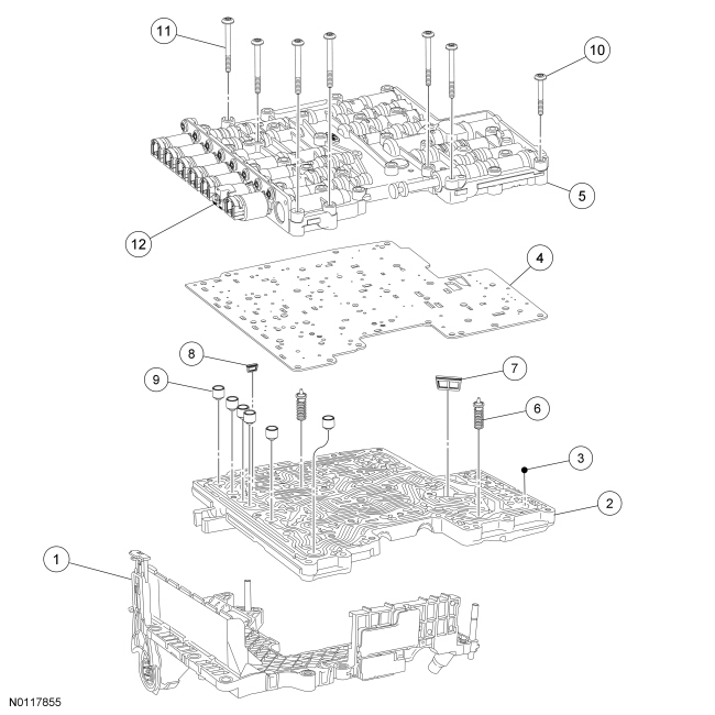
| Item | Part Number | Description |
|---|---|---|
| 1 | 7G276 | Molded leadframe |
| 2 | — | Main control valve body (upper) |
| 3 | 7E195 | Main control valve check ball (8 required) |
| 4 | 7Z490 | Main control valve body separator plate |
| 5 | — | Main control valve body (lower) |
| 6 | — | Main control valve |
| 7 | 7H187 | Main control filter |
| 8 | 7B155 | Transmission fluid filter |
| 9 | 7J191 | Transmission solenoid damper valve assembly |
| 10 | W707886 | Main control assembly short bolt — connects upper and lower half together (19 required) |
| 11 | W707884 | Main control assembly long bolt — connects molded leadframe to main control valve assembly (6 required) |
| 12 | — | Transmission shift control solenoids |
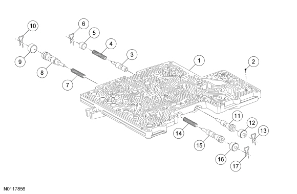
| Item | Part Number | Description |
|---|---|---|
| 1 | 7A092 | Main control valve assembly (ditch plate) (upper half) |
| 2 | 7E195 | Main control valve check ball (8 required) |
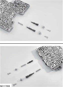
| 3 | — | Transmission clutch D2 latch valve |
| 4 | — | Transmission clutch valve spring |
| 5 | — | Transmission clutch valve spring plug |
| 6 | 7G007 | Transmission clutch valve spring plug retaining clip |
| 7 | — | Transmission clutch valve spring |
| 8 | — | Transmission clutch B regulator valve |
| 9 | — | Transmission clutch valve spring plug |
| 10 | 7G007 | Transmission clutch valve spring plug retaining clip |
| 11 | — | Transmission clutch valve |
| 12 | — | Transmission clutch valve spring plug |
| 13 | 7G007 | Transmission clutch valve spring plug retaining clip |
| 14 | — | Transmission clutch valve spring |
| 15 | — | Transmission clutch valve |
| 16 | — | Transmission clutch valve spring plug |
| 17 | 7G007 | Transmission clutch valve spring plug retaining clip |
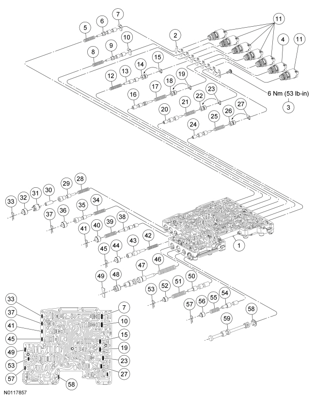
| Item | Part Number | Description |
|---|---|---|
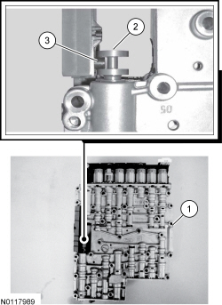
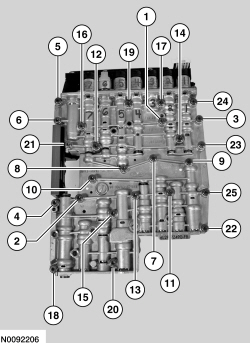
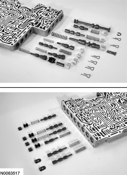
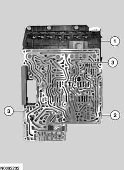
| 1 | — | Main control valve assembly (lower half) |
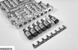
| 2 | — | Transmission shift control solenoid hold-down bracket |
| 3 | — | Transmission shift control solenoid hold-down bracket bolt M5 x 0.80 x 12 (8 required) |
| 4 | 7G484 | Transmission ON/OFF shift solenoid |
| 5 | — | Transmission clutch valve spring |
| 6 | — | Transmission clutch A latch valve |
| 7 | — | Transmission spring retainer plate |
| 8 | — | Transmission clutch valve spring |
| 9 | — | Transmission clutch B latch valve |
| 10 | 7F194 | Transmission spring retainer plate |
| 11 | 7G383 | Transmission Variable Force Solenoid (VFS) (6 required) |
| 12 | — | Transmission solenoid regulator valve spring |
| 13 | — | Transmission solenoid pressure regulator valve |
| 14 | — | Transmission solenoid plug |
| 15 | 7G007 | Transmission valve plug retainer |
| 16 | — | Transmission clutch D1 latch valve |
| 17 | — | Transmission clutch valve spring |
| 18 | — | Transmission solenoid plug |
| 19 | 7G007 | Transmission valve plug retainer |
| 20 | — | Transmission drive enable valve |
| 21 | — | Transmission solenoid valve spring |
| 22 | — | Transmission solenoid plug |
| 23 | 7G007 | Transmission valve plug retainer |
| 24 | — | Transmission solenoid multiplex valve |
| 25 | — | Transmission solenoid valve spring |
| 26 | — | Transmission solenoid plug |
| 27 | 7G007 | Transmission valve plug retainer |
| 28 | — | Transmission clutch valve spring |
| 29 | — | Transmission clutch A pressure regulator valve |
| 30 | — | Transmission clutch regulator valve sleeve |
| 31 | — | Transmission valve return plug |
| 32 | — | Transmission valve return plug |
| 33 | 7G077 | Transmission valve plug return clip |
| 34 | — | Transmission clutch valve spring |
| 35 | — | Transmission clutch E pressure regulator valve |
| 36 | — | Transmission valve return plug |
| 37 | 7G007 | Transmission valve plug return clip |
| 38 | — | Transmission clutch E latch valve |
| 39 | — | Transmission clutch control valve spring |
| 40 | — | Transmission valve return plug |
| 41 | 7G007 | Transmission valve plug return clip |
| 42 | — | Transmission bypass clutch control valve spring |
| 43 | — | Transmission bypass clutch control valve |
| 44 | — | Transmission valve return plug |
| 45 | 7G007 | Transmission valve plug return clip |
| 46 | — | Transmission manual oil pressure regulator valve spring |
| 47 | — | Transmission main oil pressure regulator valve |
| 48 | — | Transmission manual oil pressure regulator valve sleeve |
| 49 | 7G007 | Transmission valve plug return clip |
| 50 | — | Transmission converter regulator valve |
| 51 | — | Transmission converter regulator valve spring |
| 52 | — | Transmission valve return plug |
| 53 | 7G007 | Transmission valve plug return clip |
| 54 | — | Transmission lube control valve |
| 55 | — | Transmission lube control valve spring |
| 56 | — | Transmission valve return plug |
| 57 | 7G007 | Transmission valve plug return clip |
| 58 | W527007-S | Retaining ring |
| 59 | — | Transmission control manual valve |
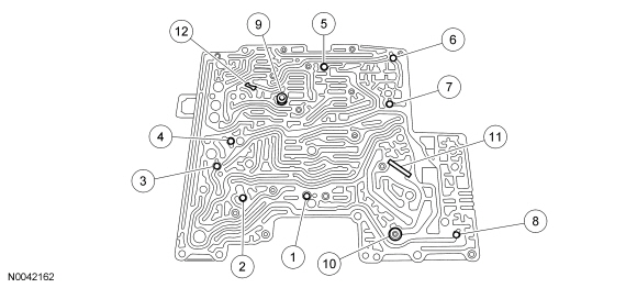
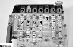
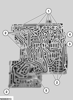
| Item | Description |
|---|---|
| 1 | Reverse/drive control check ball |
| 2 | Shift solenoid control check ball |
| 3 | Intermediate clutch exhaust control check ball |
| 4 | Direct clutch exhaust control check ball |
| 5 | Low/reverse clutch exhaust control check ball |
| 6 | Forward clutch exhaust control check ball |
| 7 | Overdrive clutch exhaust control check ball |
| 8 | Reverse exhaust control check ball |
| 9 | Clutch exhaust valve |
| 10 | Converter drain back valve |
| 11 | Large filter screen |
| 12 | Small filter screen |
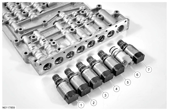
| Item | Part Number | Description |
|---|---|---|
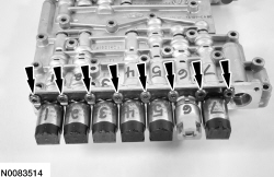
| 1 | 7G383 | Shift Solenoid A (SSA) Forward (1,2,3,4) clutch, normally low Variable Force Solenoid (VFS). |
| 2 | 7G383 | Shift Solenoid B (SSB) Direct (3,5,R) clutch, normally high VFS . |
| 3 | 7G383 | Shift Solenoid C (SSC), Intermediate (2,6) clutch, normally low VFS . |
| 4 | 7G383 | Line Pressure Control (LPC) normally high VFS . |
| 5 | 7G383 | Shift Solenoid D (SSD), low/reverse/overdrive clutch, normally high VFS . |
| 6 | 7G484 | Shift Solenoid E (SSE), normally off ON/OFF solenoid. |
| 7 | 7G383 | Torque Converter Clutch (TCC) normally low VFS . |
Disassembly
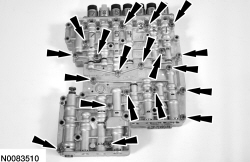
NOTE: Make an identifying mark on each solenoid and the corresponding bore for correct assembly.
NOTE: Solenoids may visually appear the same but their designs/functions are different. Use care not to assemble the main control assembly incorrectly. Incorrect solenoid installation results in poor transmission shift quality.
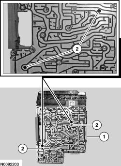
NOTE: Note the location of the 8 check balls, 6 solenoid dampers, 2 internal valves and springs and 2 filter screens for reassembly.
Main Control Upper Half
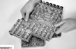
Main Control Lower Half
Assembly
Main Control Upper Half
NOTE: Many components and surfaces in the main control valve body are precision machined. Careful handling during disassembly, cleaning, inspection and assembly prevents unnecessary damage to machined surfaces.
Install the retaining clips, caps, valves and valve spring into each bore.Main Control Lower Half
NOTE: Many components and surfaces in the main control valve body are precision machined. Careful handling during disassembly, cleaning, inspection and assembly prevents unnecessary damage to machined surfaces.
Install the retaining clips, caps, valves and valve spring into each bore.NOTICE: A Variable Force Solenoid (VFS) is calibrated from the factory and are not all the same. If replacing a VFS , match the replacement solenoid type (normally high/normally low) and the band number with the original solenoid or harsh shifts or damage to the transmission can occur.
Inspect the solenoid screens for contamination and install new solenoids if needed. Lubricate the solenoid O-rings with clean transmission fluid.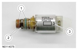
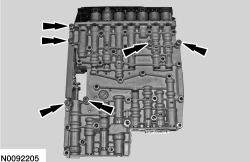
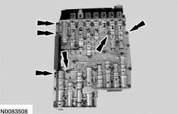
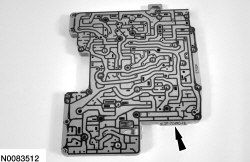
NOTICE: Toward the back of the upper valve body there is a hydraulic passage that is shaped as though it receives a check ball. This passage does not require a check ball. Be sure not to mistake this hydraulic passage for a passage that does require a check ball or damage to the transmission can occur.
Install the solenoid dampers, check balls, converter drain back valve and filter screens.
NOTICE: If the drain back valves are not installed correctly in the separator plate, damage to the transmission can occur.
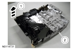
Position the new main control separator plate on the main control upper valve body.