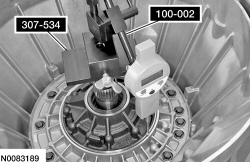
100-002 (TOOL-4201-C)

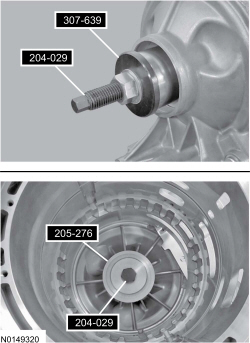
204-029 (T77F-1176)

307-534

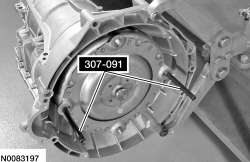
307-091 (T81P-7902-C)

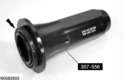
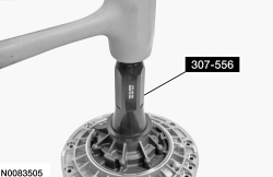
307-556

205-276 (T88T-1175-AH)

307-639

307-559

307-638

307-553

307-343 (T95P-77001-AHR)
SECTION 307-01: Automatic Transaxle/Transmission — 6R80
| 2014 Mustang Workshop Manual
|
ASSEMBLY
| Procedure revision date: 01/07/2013
|
| Dial Indicator Gauge with Holding Fixture
100-002 (TOOL-4201-C) |
| Drawbar (Heavy Duty Threaded)
204-029 (T77F-1176) |
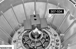
| End Play Gauge, Transmission
307-534 |
| Handle, Torque Converter
307-091 (T81P-7902-C) |
| Installer, Fluid Pump Seal
307-556 |
| Installer, Front Wheel Hub Oil Seal
205-276 (T88T-1175-AH) |
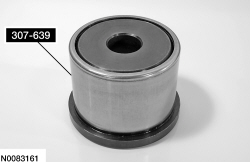
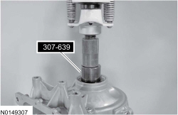
| Installer, Rear Bearing 4X2
307-639 |
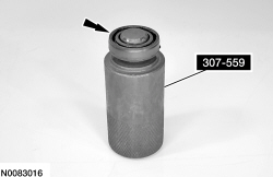
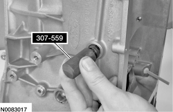
| Installer, Shifter Fluid Seal
307-559 |
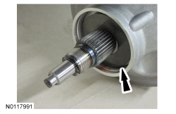
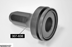
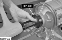
| Rear Seal Installer 4X2
307-638 |
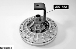
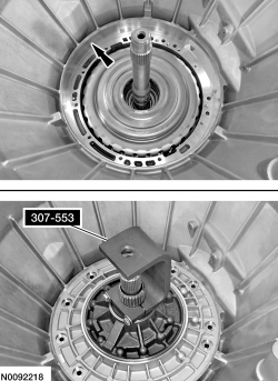
| Remover, Transmission Fluid Pump
307-553 |
| Retaining Ring Pliers
307-343 (T95P-77001-AHR) |
| Item | Specification |
|---|---|
| Motorcraft® MERCON® LV Automatic Transmission Fluid
XT-10-QLVC (US); CXT-10-LV12 (Canada) | MERCON® LV |
| Motorcraft® Multi-Purpose Grease
XL-5 | ESB-M1C93-B |
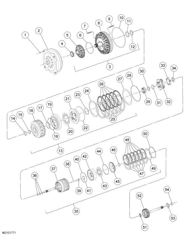
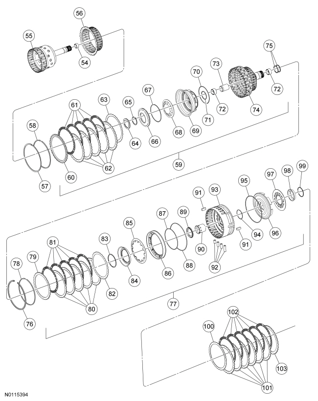
| Item | Part Number | Description |
|---|---|---|
| 1 | N800750-S437 | Flexplate-to-torque converter nut (4 required) |
| 2 | 7902 | Torque converter |
| 3 | 7A103 | Pump assembly |
| 4 | 7A248 | Front pump oil seal |
| 5 | — | Pump body (part of 7A103) |
| 6 | 7A248 | Front pump inner oil seal |
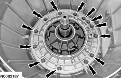
| 7 | 7N134 | Front pump-to-case bolt (13 required) |
| 8 | 7A103 | Front pump assembly |
| 9 | W707871-S300 | Bolt — attaches pump to pump adapter assembly (11 required) |
| 10 | 7A248 | Front pump outer oil seal |
| 11 | 7D019 | Clutch support fluid seal |
| 12 | 7L323 | Front pump support seal |
| 13 | — | Forward (A) clutch assembly |
| 14 | — | Forward (A) clutch rear bushing (part of 7A360) |
| 15 | 7D014 | Front pump selective washer |
| 16 | 7A360 | Forward (A) clutch cylinder and hub assembly |
| 17 | 7A548 | Forward (A) clutch inner piston seal |
| 18 | 7A548 | Forward (A) clutch outer piston seal |
| 19 | 7A262 | Forward (A) clutch piston |
| 20 | 7A480 | Forward (A) clutch piston retaining spring |
| 21 | 7H360 | Forward (A) clutch balance piston assembly |
| 22 | 7A548 | Forward (A) clutch balance piston outer seal |
| 23 | 7H365 | Forward (A) clutch balance piston snap ring |
| 24 | 7E085 | Forward (A) clutch cushion spring |
| 25 | 7E314 | Forward (A) clutch steel plates (externally splined) (quantity model dependent) |
| 26 | 7B164 | Forward (A) clutch friction plates (internally splined) (quantity model dependent) |
| 27 | 7B066 | Forward (A) clutch pressure plate |
| 28 | 7D483 | Pressure plate retaining snap ring |
| 29 | 7D063 | Front planetary sun gear (No. 1) |
| 30 | 7H375 | Bearing (T1) |
| 31 | — | Front planetary carrier assembly snap ring (part of 7A398) |
| 32 | 7A398 | Front planetary carrier assembly |
| 33 | 7L339 | Plate transmission fluid collector |
| 34 | 7L495 | Bearing (T2) |
| 35 | — | Overdrive (E) clutch assembly |
| 36 | 7G091 | Turbine shaft seals (3 required) |
| 37 | 7F207 | Input shaft |
| 38 | — | Fluid distributor sleeve (part of 7J006) |
| 39 | — | Output shaft bushing (part of 7J006) |
| 40 | 7A548 | Overdrive (E) clutch piston outer seal |
| 41 | 7A548 | Overdrive (E) clutch piston inner seal |
| 42 | 7A262 | Overdrive (E) clutch piston |
| 43 | 7B070 | Overdrive clutch piston spring |
| 44 | 7A548 | Balance piston outer seal |
| 45 | 7H360 | Overdrive (E) balance piston |
| 46 | 7C122 | Balance piston snap ring |
| 47 | 7B442 | Overdrive (E) clutch steel plates (externally splined) |
| 48 | 7B164 | Overdrive (E) clutch friction plates (internally splined) |
| 49 | 7B066 | Overdrive (E) pressure plate |
| 50 | 7D483 | Overdrive (E) clutch retaining ring |
| 51 | 7C096 | Bearing (T3) |
| 52 | 7F351 | Intermediate (C) clutch shaft |
| 53 | 7H375 | Bearing (T4) |
| 54 | — | Sun gear bushings (part of 7R193) (2 required) |
| 55 | 7B067 | Sun gear hub and shaft assembly |
| 56 | 7F236 | Direct (B) clutch hub |
| 57 | 7C122 | Direct (B) clutch cylinder retaining ring |
| 58 | 7D483 | Direct (B) clutch pressure plate retaining ring |
| 59 | — | Direct (B) clutch assembly (clutch B) |
| 60 | 7B066 | Direct (B) clutch pressure plate |
| 61 | 7B164 | Direct (B) clutch friction plates (internally splined) (quantity model dependent) |
| 62 | 7B442 | Direct (B) clutch steel plates (externally splined) (quantity model dependent) |
| 63 | 7E085 | Direct (B) clutch cushion plate |
| 64 | 7C096 | Roller bearing (T5) |
| 65 | 7A577 | Direct (B) clutch piston retaining ring |
| 66 | 7A262 | Direct (B) clutch balance piston |
| 67 | 7A548 | Direct (B) clutch balance seal |
| 68 | 7B488 | Direct (B) clutch piston return spring |
| 69 | — | Direct (B) clutch piston |
| 70 | 7A548 | Direct (B) clutch piston outer seal |
| 71 | 7C099 | Direct (B) clutch piston inner seal |
| 72 | — | Direct (B) clutch hub bushings (part of 7F283) (2 required) |
| 73 | — | Gear shaft tube sleeve (part of 7F283) |
| 74 | 7F283 | Direct (B) clutch cylinder |
| 75 | 7D020 | Shell cylinder seals (2 required) |
| 76 | 7D483 | Center support retaining ring |
| 77 | — | Intermediate (C) clutch assembly |
| 78 | 7D483 | Intermediate (C) clutch pressure plate retaining ring |
| 79 | 7B066 | Intermediate (C) clutch pressure plate |
| 80 | 7B442 | Intermediate (C) clutch steel plates (externally splined) (quantity model dependent) |
| 81 | 7B164 | Intermediate (C) clutch friction plates (internally splined) (quantity model dependent) |
| 82 | 7E085 | Intermediate (C) clutch pressure plate spring |
| 83 | 7A577 | Intermediate (C) clutch retaining ring |
| 84 | 7B043 | Intermediate (C) clutch ring |
| 85 | 7A480 | Intermediate (C) clutch piston spring |
| 86 | 7E005 | Intermediate (C) clutch piston |
| 87 | 7F225 | Intermediate (C) clutch piston inner seal |
| 88 | 7F224 | Intermediate (C) clutch piston outer seal |
| 89 | 7F373 | Bearing (T6) |
| 90 | — | Center shaft sleeve (part of support assembly) |
| 91 | 7B220 | Center support keys (2 required) |
| 92 | 7G199 | Center support seals (4 required) |
| 93 | 7G033 | Center support assembly |
| 94 | 7D404 | Low/reverse clutch piston center seal |
| 95 | 7D403 | Low/reverse clutch piston outer seal |
| 96 | 7A262 | Low/reverse clutch piston |
| 97 | 7B070 | Low/reverse clutch piston return spring |
| 98 | 7H318 | Low/reverse clutch piston retainer |
| 99 | 7D483 | Retainer transmission-snap ring |
| 100 | 7E085 | Clutch disc cushion plate |
| 101 | 7B442 | Low/reverse clutch steel plates (externally splined) |
| 102 | 7B164 | Low/reverse clutch friction plates (internally splined) |
| 103 | 7B066 | Low/reverse clutch pressure plate (select fit) |
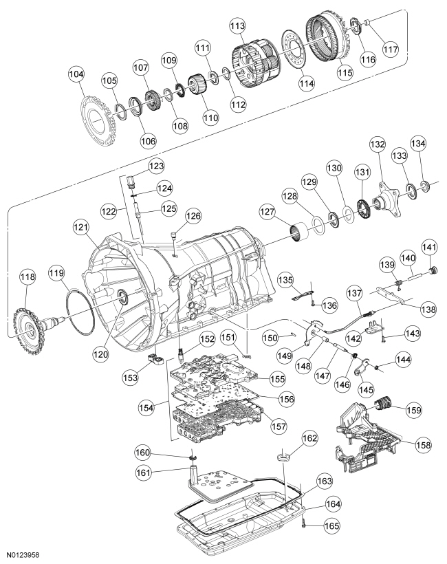
| 104 | 7A089 | One-Way Clutch (OWC) |
| 105 | 7F405 | Thrust gear shim (select fit) |
| 106 | 7C041 | Thrust bearing (T7) |
| 107 | 7D063 | Sun gear No. 2 |
| 108 | 7D235 | Thrust bearing outer race |
| 109 | 7D234 | Roller bearing (T8) |
| 110 | 7D063 | Sun gear No. 3 |
| 111 | 7D234 | Roller bearing (T9) |
| 112 | — | Roller bearing race (T9) |
| 113 | 7D006 | Rear planetary carrier assembly |
| 114 | — | Fluid collar rear planetary plate (part of 7D006) |
| 115 | 7A153 | Output shaft ring gear assembly |
| 116 | 7G178 | Thrust Bearing (T10) |
| 117 | — | Output shaft bushing (part of 7060) |
| 118 | 7060 | Output shaft park gear assembly |
| 119 | 7N194 | Output shaft retaining ring |
| 120 | 7B368 | Bearing (T11) |
| 121 | 7005 | Transmission case assembly (model dependent) |
| 122 | 7A010 | Transmission case fluid fill plug assembly |
| 123 | 7H398 | Transmission case fluid fill plug |
| 124 | 7A010 | Transmission case fluid fill seal |
| 125 | 7A010 | Transmission oil level indicator |
| 126 | 7034 | Transmission case vent assembly (model dependent) |
| 127 | 7A415 | Output shaft bearing assembly |
| 128 | 7A433 | Washer |
| 129 | 7B368 | Thrust bearing (T12) |
| 130 | 7N357 | Slip plane washer |
| 131 | 7052 | Extension housing seal |
| 132 | 7089 | Output shaft flange |
| 133 | 7052 | Extension housing flange seal |
| 134 | 7045 | Output shaft flange retaining nut |
| 135 | 7E332 | Manual valve detent spring |
| 136 | W711235-S300 | Manual valve detent spring retaining screw and washer |
| 137 | 7A232 | Park pawl actuator rod |
| 138 | 7A441 | Park pawl |
| 139 | 7D070 | Park pawl return spring |
| 140 | 7D071 | Park pawl shaft |
| 141 | 7H398 | Plug assembly transmission case housing |
| 142 | 7G101 | Park rod actuating plate |
| 143 | W711235-S300 | Park pawl abutment retaining screw and washer |
| 144 | W708455-S441 | Manual control lever nut |
| 145 | 7A256 | Manual control lever |
| 146 | 7B498 | Manual control lever shaft seal |
| 147 | 7C493 | Manual control lever shaft |
| 148 | 7A209 | Manual control lever shaft spacer |
| 149 | 7A115 | Manual valve detent lever assembly |
| 150 | 7G100 | Manual valve detent lever retaining pin |
| 151 | 7F277 | One-Way Clutch (OWC) bias spring |
| 152 | 7H322 | Thermal bypass valve |
| 153 | 7F401 | Front pump adapter seal |
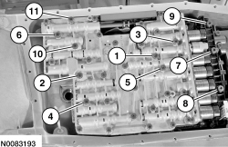
| 154 | 7A100 | Main control assembly |
| 155 | — | Main control valve body assembly (part of 7A100) |
| 156 | 7Z490 | Main control valve body separator plate |
| 157 | — | Lower main control valve body (part of 7A100) |
| 158 | 7G276 | Molded leadframe |
| 159 | 7G276 | Bulkhead connector sleeve |
| 160 | — | Transmission fluid filter seal (part of 7A098) |
| 161 | 7A098 | Transmission fluid filter |
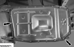
| 162 | — | Transmission fluid pan magnet |
| 163 | 7A191 | Transmission fluid pan gasket |
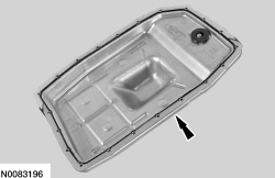
| 164 | 7A194 | Transmission fluid pan |
| 165 | W500214-S437 | Transmission fluid pan bolt |
NOTE: Clutch plate quantity is model dependant based on engine displacement. Refer to Clutch Plate Quantity chart in the Specifications portion of this section.
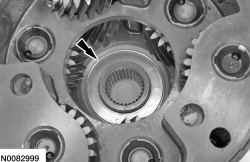
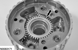
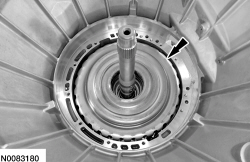
NOTE: When installing the sun gear, make sure that the TAPERED EDGE is facing UP toward the torque converter housing.
Install the sun gear into the planetary assembly.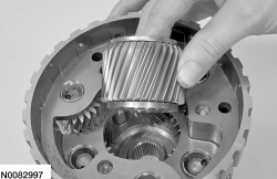
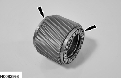
NOTE: Place the manual lever in PARK when installing the rear planetary gearset to hold the rear ring gear stationary.
Install the planetary carrier.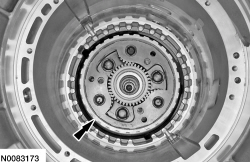
NOTE: Friction and steel plate quantity are model dependent and vary based on engine displacement. For additional information, refer to the Clutch Plate Quantity Chart in the Specifications portion of this section.
Soak the low/reverse clutch plates in clean automatic transmission fluid.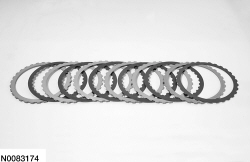
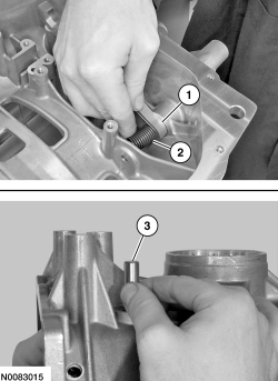
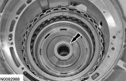
NOTE: Inspect the T7 thrust bearing and selective shim for damage or scoring.
Install the T7 thrust bearing and install the selective shim on the T7 thrust bearing.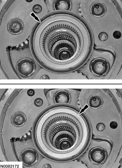
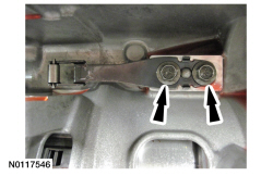
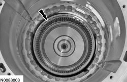
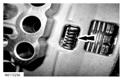
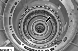
NOTE: Align the OWC in the transmission case so the bias spring fits into the transmission case.
Install the OWC as shown so the bias spring can be installed as shown.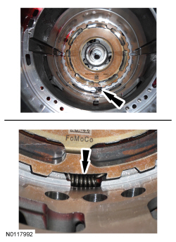
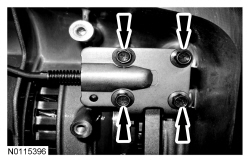
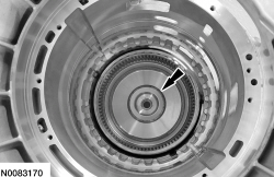
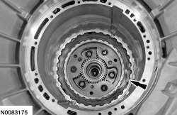
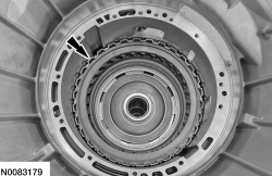
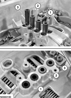
NOTE: Make sure that when installing the center support the feed holes on the center support are lined up with the feed holes in the case.
Install the center support into the case.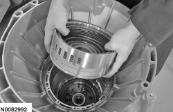
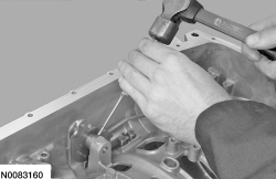
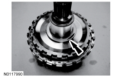
NOTICE: Install the snap ring with the beveled surface facing up and the snap ring gap in the 3 o'clock or the 9 o'clock position.
Using the Retaining Ring Pliers, install the center support snap ring. Make sure the snap ring is fully seated.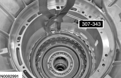
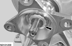
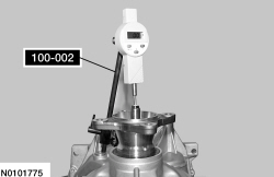
NOTE: Loosely install the flange nut or an inaccurate reading may be recorded.
Using the Dial Indicator Gauge with Holding Fixture, lift up on the output shaft flange and record the reading. The reading should be within 0.6-0.9 mm (0.024-0.035 in).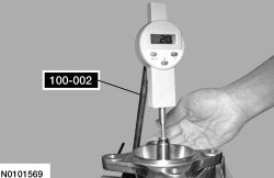
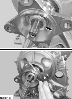
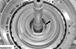
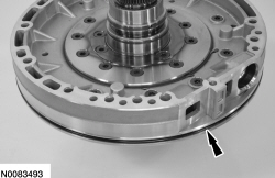
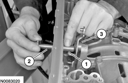
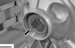
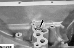
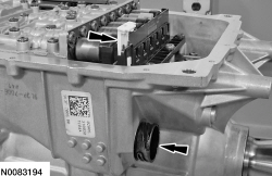
NOTE: Make sure the transmission fluid filter seal has been removed. If it has not, use a suitable pick and remove the seal.
NOTE: Add 0.118L (4 oz) of clean transmission fluid to prime the pump.
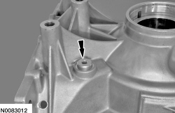
Install the front pump adapter seal and prime the fluid pump.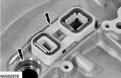
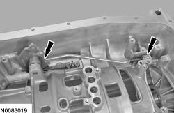
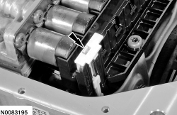
NOTE: The main control will not lay flush on the case, this is a normal condition with the rubber feed tubes, the bolts will pull the mechatronic assembly down.
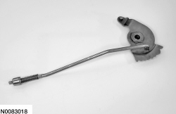
Slightly lift the main control assembly and align the manual valve in the manual valve linkage and position the main control in place.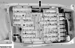
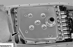
NOTE: The fluid pan gasket can be reused if not damaged.
Install a new transmission fluid pan gasket if required.