
SECTION 308-01: Clutch
| 2014 Mustang Workshop Manual
|
REMOVAL AND INSTALLATION
| Procedure revision date: 01/07/2013
|
|
Vehicle Communication Module (VCM) and Integrated Diagnostic System (IDS) software with appropriate hardware, or equivalent scan tool
|
| Item | Part Number | Description |
|---|---|---|
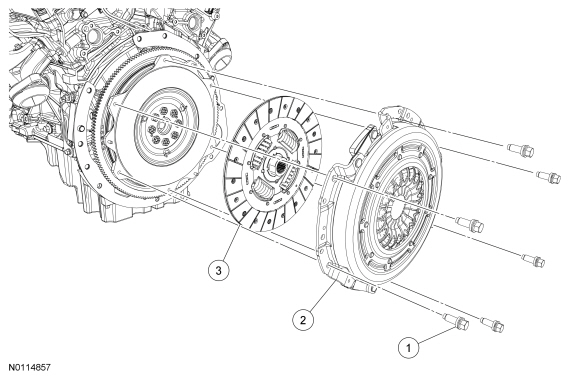
| 1 | W715869 | Clutch pressure plate bolt (6 required) |
| 2 | 7563 | Clutch pressure plate |
| 3 | 7550 | Clutch disc |
Removal
 WARNING: Do not breathe dust or use compressed air to blow dust from storage containers or friction components. Remove dust using government-approved techniques. Friction component dust may be a cancer and lung disease hazard. Exposure to potentially hazardous components may occur if dusts are created during repair of friction components, such as brake pads and clutch discs. Exposure may also cause irritation to skin, eyes and respiratory tract, and may cause allergic reactions and/or may lead to other chronic health effects. If irritation persists, seek medical attention or advice. Failure to follow these instructions may result in serious personal injury.
NOTICE: If the parts are to be reused, index-mark the pressure plate to the flywheel. Failure to install the pressure plate to the flywheel in the original position may result in a clutch system vibration.
NOTICE: Loosen the bolts evenly to prevent clutch pressure plate damage.
Remove the 6 pressure plate bolts by turning them 1 turn at a time in a star pattern until the clutch is fully released. Remove the pressure plate and the clutch disc.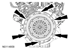
Installation
NOTE: The dual mass flywheel has 7 degrees (3.25 ring gear teeth) of freeplay in the clockwise and counter clockwise direction, this is normal between the primary part of the flywheel (bolts-to-crankshaft) and the secondary part of the flywheel (clutch-to-ring gear).
Inspect the flywheel. Refer to Section 303-00 .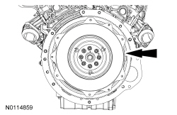
NOTICE: If installing a new pressure plate and/or flywheel, align the paint dot on the pressure plate as close as possible to the paint dot on the flywheel or a clutch system vibration can occur.
NOTICE: If installing the original pressure plate, align it using the index-marks made during removal or a clutch system vibration can occur.
NOTE: Always install new pressure plate bolts.
Using a clutch aligner, position the clutch disc on the flywheel. If installing the original pressure plate, align the pressure plate to the flywheel using the index-marks made during removal. If installing a new pressure plate, align the pressure plate to the flywheel using the paint dots. Install the 6 new pressure plate bolts by turning the bolts 1 turn at a time in a star pattern until the clutch is fully secured.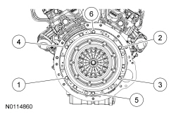
NOTE: Before securing the transmission to the engine, connect the clutch hydraulic tube to the slave cylinder.
Install the transmission. Refer to Section 308-03A .