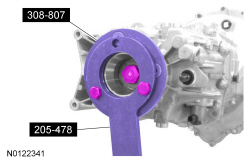
205-478

308-807

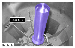
308-806

308-808

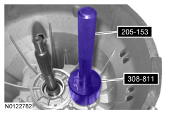
308-811

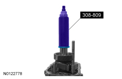
308-809
SECTION 308-03A: Manual Transaxle/Transmission — MT82 Getrag 6-Speed
| 2014 Mustang Workshop Manual
|
ASSEMBLY
| Procedure revision date: 01/07/2013
|
| Holding Tool, Drive Pinion Flange
205-478 |
| Holding Tool, Rear Flange
308-807 |
| Installer, Front Seal
308-806 |
| Installer, Rear Flange
308-808 |
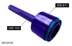
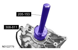
| Installer, Rear Seal
308-811 |
| Installer, Synchro Gear Pack
308-809 |
| Item | Specification |
|---|---|
| Motorcraft® Gasket Maker
TA-16 | WSK-M2G348-A5 |
| Motorcraft® Dual Clutch Transmission Fluid
XT-11-QDC | WSS-M2C200-D2 |
| Motorcraft® Threadlock 262
TA-26 | WSK-M2G351-A6 |
| Motorcraft® Threadlock and Sealer
TA-25 | WSK-M2G351-A5 |
NOTE: Refer to the on-line Workshop Manual to learn about using an Interactive Illustration.
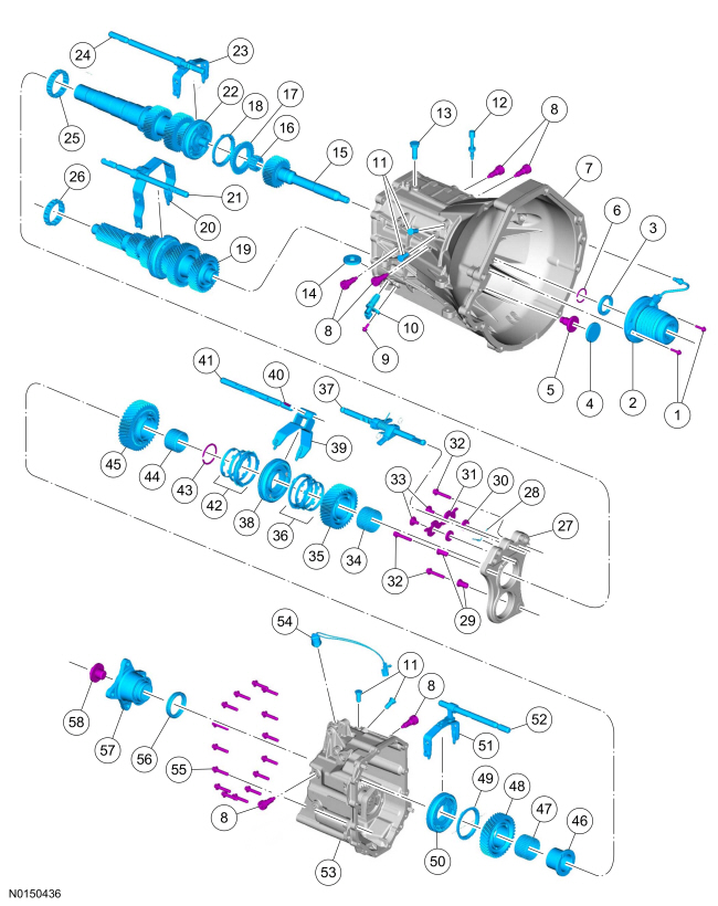
| Item | Part Number | Description |
|---|---|---|
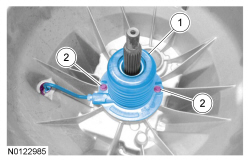
| 1 | — | Clutch slave cylinder bolt (2 required) |
| 2 | 7A508 | Clutch slave cylinder |
| 3 | 7048 | Input shaft seal |
| 4 | 7A010 | Countershaft bolt cover |
| 5 | 7L013 | Countershaft bolt |
| 6 | 7064 | Input shaft snap ring |
| 7 | — | Front transmission case assembly |
| 8 | 7A443 | Shift fork pivot bolts (6 required) |
| 9 | W714875 | OSS sensor bolt |
| 10 | 7H103 | OSS sensor |
| 11 | 7M131 | Shift rail detents (4 required) |
| 12 | 7K341 | Transmission case vent tube |
| 13 | 7C031 | Shift shaft stop pin |
| 14 | 7L027 | Magnet |
| 15 | 7017 | Input shaft |
| 16 | 7C043 | Output shaft roller bearing |
| 17 | 7M000 | 5th gear synchronizer cone |
| 18 | 7107 | 5th gear synchronizer ring |
| 19 | — | Countershaft assembly |
| 20 | 7230 | 3rd/4th shift fork |
| 21 | 7241 | 3rd/4th shift rail |
| 22 | — | Output shaft assembly |
| 23 | 7230 | 5th/6th shift fork |
| 24 | 7242 | 5th/6th shift rail |
| 25 | 7025 | Center support bearing (output shaft) |
| 26 | 7025 | Center support bearing (countershaft) |
| 27 | 7J086 | Center support |
| 28 | 7234 | Spring |
| 29 | 7K024 | Dowels (2 required) |
| 30 | 7J172 | Spacers (2 required) |
| 31 | 7K201 | Interlock plate |
| 32 | W715104 | Center support bolts (3 required) |
| 33 | 7A443 | Interlock plate bolts (2 required) |
| 34 | 7M037 | 2nd gear needle bearing |
| 35 | 7102 | 2nd gear |
| 36 | 7107 | 2nd gear synchronizer ring assembly |
| 37 | 7210 | Shift shaft assembly |
| 38 | 7124 | 1st/2nd gear synchronizer assembly |
| 39 | 7230 | 1st/2nd shift fork |
| 40 | 7C031 | Roll pin |
| 41 | 7240 | 1st/2nd shift rail |
| 42 | 7107 | 1st gear synchronizer ring assembly |
| 43 | 7064 | 1st/2nd gear synchronizer assembly snap ring |
| 44 | 7M037 | 1st gear needle bearing |
| 45 | 7100 | 1st gear |
| 46 | 7N168 | Reverse gear needle bearing race |
| 47 | 7M037 | Reverse gear needle bearing |
| 48 | 7C238 | Reverse gear |
| 49 | 7107 | Reverse gear synchronizer ring |
| 50 | 7124 | Reverse gear synchronizer assembly |
| 51 | 7230 | Reverse shift fork |
| 52 | 7241 | Reverse shift rail |
| 53 | — | Rear transmission case assembly |
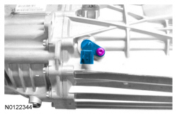
| 54 | 15520 | Reverse lamp switch |
| 55 | W715103 | Transmission case bolts |
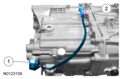
| 56 | 7052 | Output shaft seal |
| 57 | 7K177 | Output shaft flange |
| 58 | 7L013 | Output shaft flange bolt |
NOTICE: Lubricate all components with the recommended transmission fluid before assembling.
NOTICE: Do not heat the input shaft bearing higher than 120°C (248°F) maximum or damage to the input shaft bearing can occur.
Using a heat gun, heat the input shaft bearing inner race to a maximum of 120°C (248°F).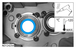
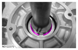
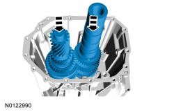
NOTICE: Make sure the small diameter side of the output shaft roller bearing cage is facing the input shaft or damage to the output shaft bearing can occur.
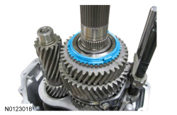
With the small diameter side of the output shaft roller bearing cage facing the input shaft, install the output shaft roller bearing.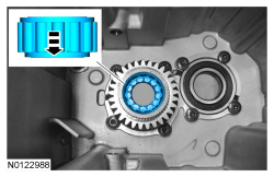
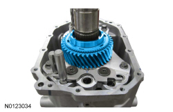
NOTE: Apply petroleum jelly to hold the 5th gear synchronizer ring and the 5th gear synchronizer cone in place during assembly.
Install the 5th gear synchronizer ring and the 5th gear synchronizer cone.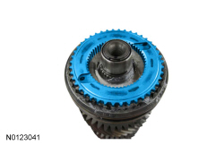
NOTICE: Do not heat the countershaft bearing higher than 120°C (248°F) maximum or damage to the countershaft bearing can occur.
Using a heat gun, heat the countershaft bearing inner race to a maximum of 120°C (248°F).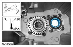
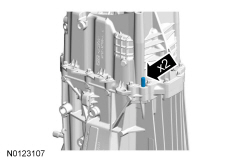
NOTICE: Make sure the shift fork pivot bolts engage into the shift fork or damage to the shift fork can occur.
Install the 5th/6th shift fork, the 5th/6th shift rail and loosely install the shift fork pivot bolts.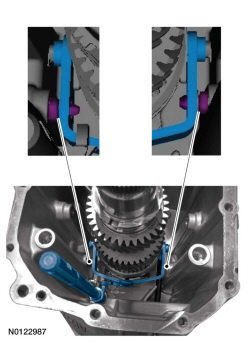
NOTICE: Make sure the shift fork pivot bolts engage into the shift fork or damage to the shift fork can occur.
Install the 3rd/4th shift fork, the 3rd/4th shift rail and loosely install the shift fork pivot bolts.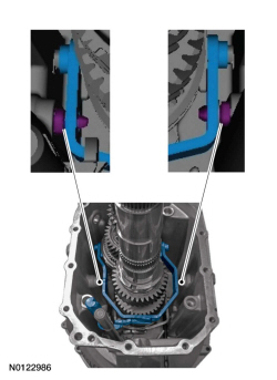
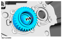
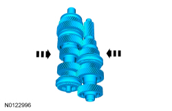
NOTICE: When installing the bearings, do not over expand the bearing cages or damage to the bearing cages can occur.
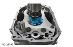
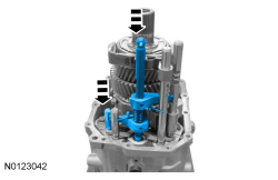
Slightly expand the center support bearing cages and slide the center support bearings down the shaft assemblies. Lock the bearing cage tabs.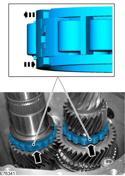
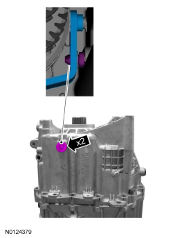
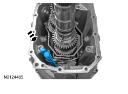
NOTICE: Install the counter shaft bolt with the transmission in the vertical position with the input shaft facing down.
Install the countershaft bolt.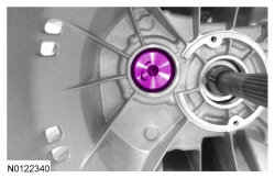

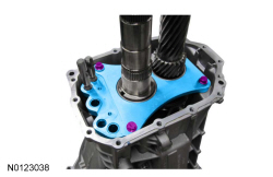
NOTICE: The center support must be tightened evenly or damage to the center support or transmission case can occur.
Install the center support and evenly tighten the 3 center support bolts.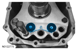
NOTE: Make sure the interlock plate moves freely.
Install the interlock plate and the 2 interlock plate bolts.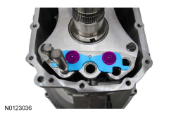
NOTICE: The 6 synchronizer ring tabs must engage into the 6 gear slots or damage to the synchronizer ring assembly can occur.
NOTE: The 2nd gear synchronizer ring assembly outer ring has 2 identification notches.
Install the 2nd gear synchronizer ring assembly.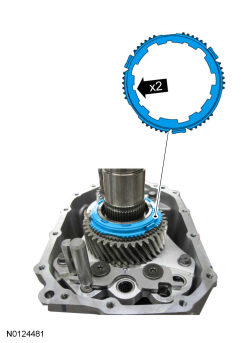
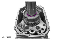
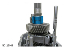
NOTICE: The 3 synchronizer ring tabs must engage into the 3 synchronizer hub slots or damage to the synchronizer hub and the synchronizer ring assembly can occur.
NOTICE: The long shoulder of the 1st/2nd synchronizer hub must be facing 2nd gear or damage to the synchronizer hub can occur.
With the long shoulder of the 1st/2nd synchronizer hub facing 2nd gear, use the Synchro Gear Pack Installer and install the 1st/2nd synchronizer hub.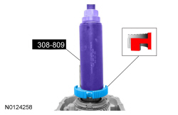
NOTE: Align the index marks made during removal on the synchronizer sleeve and the synchronizer hub.
With the groove on the 1st/2nd synchronizer sleeve facing 2nd gear, install the 1st/2nd shift fork the 1st/2nd shift rail and the 1st/2nd synchronizer sleeve.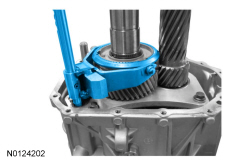
NOTE: Slide the synchronizer sleeve up to install the pressure pieces.
Install the 3 pressure pieces.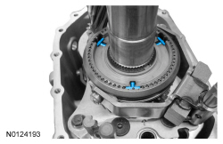
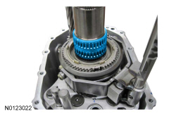
NOTICE: The 3 synchronizer ring tabs must engage into the 3 synchronizer assembly slots or damage to the synchronizer assembly and the synchronizer ring assembly can occur.
NOTE: The 1st gear synchronizer ring assembly outer ring has one identification notch.
Install the 1st gear synchronizer ring assembly.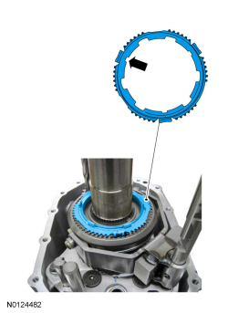
NOTICE: The 6 synchronizer ring tabs must engage into the 6 gear slots or damage to the synchronizer assembly and synchronizer ring assembly can occur.
Install the 1st gear.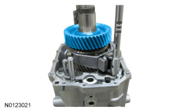
NOTICE: The shift shaft must be installed in the neutral position prior to installing the shift shaft stop pin or damage to the shift shaft stop pin can occur.
Install the shift shaft in the neutral position, using a soft-faced hammer install the shift shaft stop pin.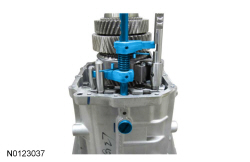
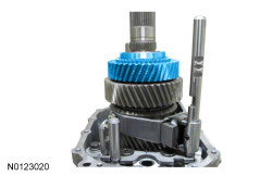
NOTICE: The 3 synchronizer ring tabs must engage into the 3 synchronizer assembly slots or damage to the synchronizer assembly and the synchronizer ring can occur.
Using the Synchro Gear Pack Installer, install the reverse gear synchronizer assembly.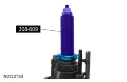
NOTE: To install the reverse shift fork and the reverse shift rail assembly, the transmission must be in neutral and the groves on the shift rails must be aligned with the interlock plate.
Install the reverse shift fork and the reverse shift rail assembly.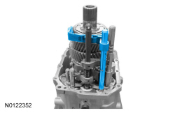
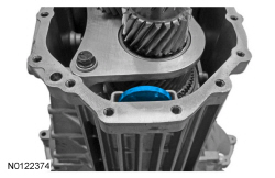
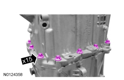
NOTE: Do not wait longer than 10 minutes to install the rear transmission case assembly due to the rapid cure time of the sealant.
Clean the sealing surfaces of the front transmission case and the sealing surfaces of the rear transmission case. Thinly coat the sealing surface of the front transmission case assembly and the sealing surface of the rear transmission case assembly with Gasket Maker.NOTICE: The rear transmission case assembly must be installed evenly with the transmission shifted into 4th gear, do not allow the shift rails to bind during installation or damage to the transmission case assembly can occur.
Using the Synchro Gear Pack Installer and the Rear Flange Installer, install the rear transmission case assembly.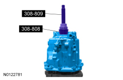
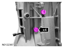
NOTICE: Make sure the shift fork pivot bolts engage into the shift fork or damage to the shift fork can occur.
Install the 2 shift fork pivot bolts.