307-569
SECTION 308-03B: Manual Transaxle/Transmission — TR6060
| 2014 Mustang Workshop Manual
|
REMOVAL
| Procedure revision date: 01/07/2013
|
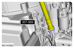
| Disconnect Tool, Transmission Cooler Line
307-569 |
| Item | Specification |
|---|---|
| Thread Sealant with PTFE
TA-24 | WSK-M2G350-A2 |
 WARNING: Do not breathe dust or use compressed air to blow dust from storage containers or friction components. Remove dust using government-approved techniques. Friction component dust may be a cancer and lung disease hazard. Exposure to potentially hazardous components may occur if dusts are created during repair of friction components, such as brake pads and clutch discs. Exposure may also cause irritation to skin, eyes and respiratory tract, and may cause allergic reactions and/or may lead to other chronic health effects. If irritation persists, seek medical attention or advice. Failure to follow these instructions may result in serious personal injury.

NOTE: Index-mark the driveshaft flange and pinion flange, and the driveshaft flange and transmission output shaft flange.
Remove the driveshaft. Refer to Section 205-01 .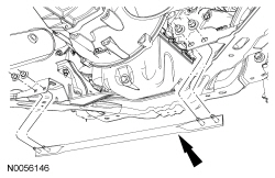
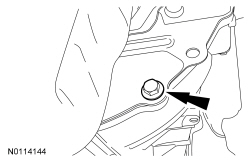
NOTE: If transmission disassembly is required, drain the transmission fluid.
Remove the drain plug and drain the transmission fluid.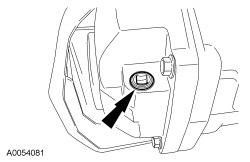
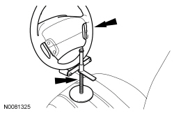
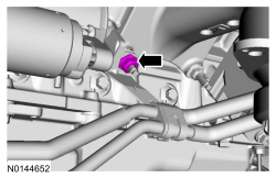
NOTICE: Do not allow the steering wheel to rotate while the steering column intermediate shaft is disconnected or damage to the clockspring can result. If there is evidence that the wheel has rotated, remove and recenter the clockspring. For additional information, refer to Section 501-20B .
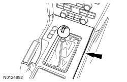
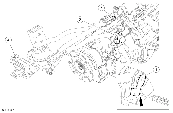
Remove and discard the steering column shaft pinch bolt and disconnect the steering column shaft.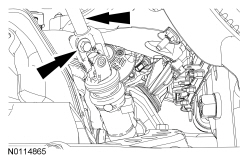
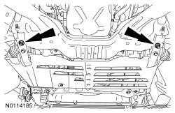
NOTE: Mark the bolts and the crossmember for assembly reference.
NOTE: LH shown, RH similar.
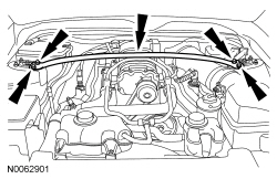
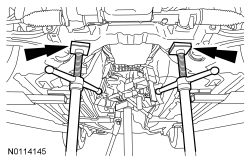
Remove the 4 rear subframe bolts.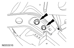
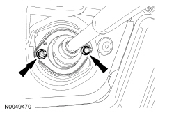
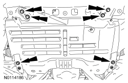
NOTE: LH shown, RH similar.
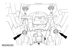
Loosen but do not remove the 4 front subframe nuts.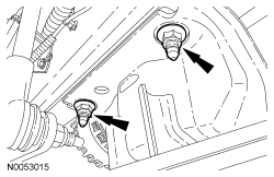
NOTICE: Do not spill brake fluid on painted or plastic surfaces or damage to the surface may occur. If brake fluid is spilled onto a painted or plastic surface, immediately wash the surface with water.
Release the clutch hydraulic tube clip and disconnect the clutch hydraulic tube from the clutch slave cylinder connector.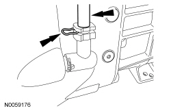
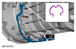
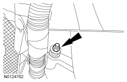
NOTE: Use a Jiffy-tite quick disconnect tool.
Disconnect the cooler tube from the transmission connector.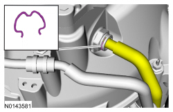
WARNING: Always secure transmission, transfer case, and axle assemblies to their service jack. Avoid obstructions while lowering and raising the jack. Improperly secured assemblies or contact with obstructions may cause the assembly to fall off the jack, which could result in serious personal injury.
NOTICE: Disconnect the wiring harness clip from the top of the transmission before rotating the transmission.
Using the transmission jack, rotate the transmission 45 degrees clockwise. Pull the transmission rearward until the input shaft is clear of the pressure plate, then lower the transmission from the vehicle.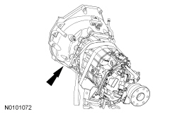
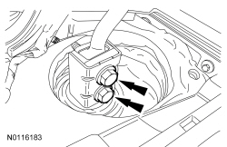
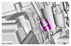
NOTE: Use a Jiffy-tite quick disconnect tool.
If necessary, disconnect the cooler tube from the transmission connector.