
205-D064 (D84L-1123-A)

308-025 (T75L-7025-C)
SECTION 308-03B: Manual Transaxle/Transmission — TR6060
| 2014 Mustang Workshop Manual
|
DISASSEMBLY AND ASSEMBLY OF SUBASSEMBLIES
| Procedure revision date: 01/07/2013
|
| Puller, Bearing
205-D064 (D84L-1123-A) |
| Remover/Installer, Bearing Tube
308-025 (T75L-7025-C) |
| Item | Specification |
|---|---|
| MERCON® V Automatic Transmission Fluid
XT-5-QM (or XT-5-QMC) (US); CXT-5-LM12 (Canada) | MERCON® V |
Disassembly
| Item | Part Number | Description |
|---|---|---|
| 1 | 7025 | Axial thrust washer |
| 2 | 7A082 | Snap ring |
| 3 | 7124 | 3rd/4th gear synchronizer assembly |
| 4 | 7107 | 3rd gear synchronizer ring assembly |
| 5 | — | Synchronizer ring (part of 7107) |
| 6 | — | Synchronizer outer cone (part of 7107) |
| 7 | — | Synchronizer inner cone (part of 7107) |
| 8 | 7117 | Spacer |
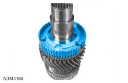
| 9 | 7B340 | 3rd gear |
| 10 | 7M037 | 3rd gear needle bearing |
| 11 | 7061 | Output shaft |
| 12 | 7102 | 2nd gear |
| 13 | 7M037 | 2nd gear needle bearing |
| 14 | 7117 | Spacer |
| 15 | 7107B | 2nd gear synchronizer ring assembly |
| 16 | — | Synchronizer inner cone (part of 7107) |
| 17 | — | Synchronizer outer cone (part of 7107) |
| 18 | — | Synchronizer ring (part of 7107) |
| 19 | 7124A | 1st/2nd gear synchronizer assembly |
| 20 | 7A082A | Split ring |
| 21 | 7A082A | Retainer |
| 22 | 7107A | 1st gear synchronizer ring assembly |
| 23 | — | Synchronizer ring (part of 7107) |
| 24 | — | Synchronizer outer cone (part of 7107) |
| 25 | — | Synchronizer inner cone (part of 7107) |
| 26 | 7100 | 1st gear |
| 27 | 7025 | 1st gear needle bearing |
| 28 | 7025 | Output shaft rear bearing |
| 29 | 7L047 | 6th driven gear |
NOTE: Slide the synchronizer sleeve up while removing the pressure pieces.
Remove the 3rd/4th gear synchronizer sleeve, the 3 pressure pieces and the axial thrust washer.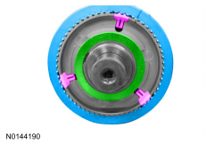
NOTICE: Hand-tighten the Bearing Puller to prevent gear damage.
NOTICE: Support the output shaft while using the press to prevent damage to the shaft or gears.
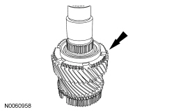
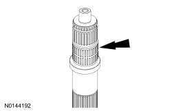
Using the Bearing Puller and a press, remove the 1st gear, the output shaft rear bearing and the 6th driven gear.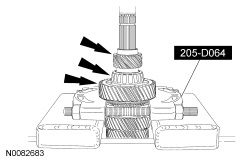
NOTE: Note the position of each synchronizer ring component before removal.
Remove the 1st gear synchronizer ring assembly.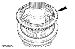
NOTE: Slide the synchronizer sleeve up while removing the pressure pieces.
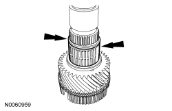
Remove the 1st/2nd gear synchronizer sleeve and the 3 pressure pieces.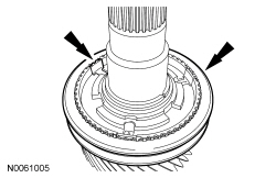
NOTE: Note the position of each synchronizer ring component before removal.
Remove the 2nd gear synchronizer ring assembly.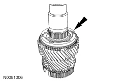
NOTICE: Hand-tighten the Bearing Puller to prevent gear damage.
NOTICE: Support the output shaft while using the press to prevent damage to the shaft or gears.
NOTE: Note the position of each synchronizer ring component before removal.
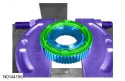
Using the Bearing Puller, remove the 3rd/4th gear synchronizer hub, the 3rd gear synchronizer ring assembly and the 3rd gear.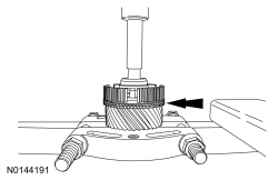
Assembly
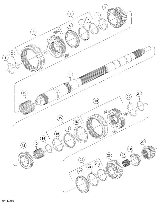
NOTE: Align the synchronizer ring tabs with the gear slots.
Install the 3rd gear, the spacer and the 3rd gear needle bearing.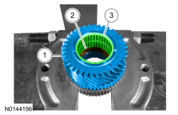
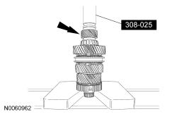
NOTICE: Align the synchronizer hub splines with the output shaft splines before using the press or damage to the synchronizer hub can occur.
Using the Bearing Puller, press the output shaft into place.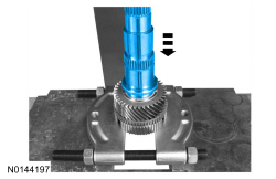
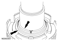
NOTICE: The marked side of the 1st/2nd gear synchronizer sleeve must face the 2nd gear, or transmission shifting concerns will occur.
NOTE: Slide the synchronizer sleeve down while installing the pressure pieces.
Install the 1st/2nd gear synchronizer sleeve and the 3 pressure pieces.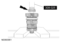
NOTICE: The marked side of the 3rd/4th gear synchronizer sleeve must face the 4th gear, or transmission shifting concerns will occur.
NOTE: Slide the synchronizer sleeve on while installing the pressure pieces.
Install the 3rd/4th gear synchronizer sleeve, the 3 pressure pieces and the axial thrust washer.