100-002 (TOOL-4201-C) or equivalent

308-021 (T75L-4201-A)

205-153 (T80T-4000-W)

307-003 (T57L-500-B)

308-254 (T96T-77110-A2 )

204-161 (T97P-1175-A)

308-220 (T94P-7025-AH)

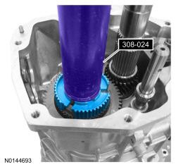
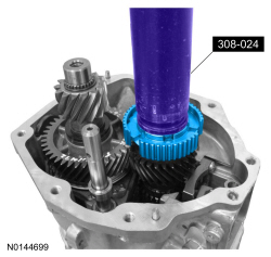
308-024 (T75L-7025-B)
SECTION 308-03B: Manual Transaxle/Transmission — TR6060
| 2014 Mustang Workshop Manual
|
ASSEMBLY
| Procedure revision date: 01/07/2013
|
| Dial Indicator Gauge with Holding Fixture
100-002 (TOOL-4201-C) or equivalent |
| Gauge, Clutch Housing
308-021 (T75L-4201-A) |
| Handle
205-153 (T80T-4000-W) |
| Holding Fixture, Transmission
307-003 (T57L-500-B) |
| Installer, Transmission Extension Housing Bushing
308-254 (T96T-77110-A2 ) |
| Installer, Halfshaft
204-161 (T97P-1175-A) |
| Installer, Input Shaft Oil Seal
308-220 (T94P-7025-AH) |
| Remover/Installer, Bearing Tube
308-024 (T75L-7025-B) |
| Item | Specification |
|---|---|
| MERCON® V Automatic Transmission Fluid
XT-5-QM (or XT-5-QMC) (US); CXT-5-LM12 (Canada) | MERCON® V |
| Threadlock and Sealer
TA-25 | WSK-M2G351-A5 |
| Thread Sealant with PTFE
TA-24 | WSK-M2G350-A2 |
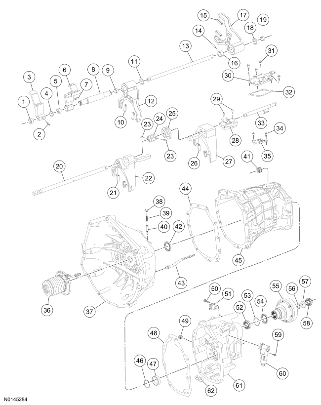
| Item | Part Number | Description |
|---|---|---|
| 1 | 7W425 | Shift rail bushing |
| 2 | 7A082 | Roll pin |
| 3 | 7241 | Reverse shift rail lever |
| 4 | 7A082 | Snap ring |
| 5 | 7W425 | Shift rail bushing |
| 6 | 7241 | 5th/6th outer shift rail lever |
| 7 | 7241 | 5th/6th outer shift lever pad |
| 8 | 7241 | 5th/6th inner shift rail lever |
| 9 | 7W425 | Shift rail bushing |
| 10 | 7L082 | 5th/6th shift fork pad |
| 11 | 7241 | Washer |
| 12 | 7230 | 5th/6th shift fork |
| 13 | 7241 | Reverse shift rail |
| 14 | 7A082 | Roll pin |
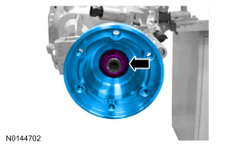
| 15 | 7L082 | Reverse shift fork pad |
| 16 | 7241 | Shift rail collar |
| 17 | 7230 | Reverse shift fork |
| 18 | 7241 | Washer |
| 19 | 7W425 | Shift rail bushing |
| 20 | 7L267 | 1st/2nd, 3rd/4th shift rail |
| 21 | 7L082 | 3rd/4th shift fork pad |
| 22 | 7230 | 3rd/4th shift fork |
| 23 | 7A082 | Roll pins |
| 24 | 7814 | Selector pin |
| 25 | 7K201 | Interlock plate |
| 26 | 7L082 | 1st/2nd shift fork pad |
| 27 | 7230 | 1st/2nd shift fork |
| 28 | — | Shift gate |
| 29 | 7A082 | Roll pins |
| 30 | 7C453 | Shift detent cover |
| 31 | — | Shift detent cover bolt (4 required) |
| 32 | — | Shift detent cover gasket |
| 33 | — | Reverse shift rail, |
| 34 | — | Shift guide plate bolt (2 required) |
| 35 | 7F476 | Shift guide plate |
| 36 | 7A508 | Clutch slave cylinder |
| 37 | 6392 | Clutch housing |
| 38 | 7234 | Shift detent plug |
| 39 | 7234 | Shift detent spring |
| 40 | 7234 | Shift detent |
| 41 | 7127 | Top shift rail bearing |
| 42 | 7052 | Input shaft seal |
| 43 | — | Oil pump pickup tube |
| 44 | — | Transmission main case-to-clutch housing gasket |
| 45 | 7005 | Transmission main case |
| 46 | 7A082 | Snap ring |
| 47 | 7025 | Output shaft bearing cup |
| 48 | — | Extension housing gasket |
| 49 | 7A010 | Case plug |
| 50 | 7A443 | OSS sensor bolt |
| 51 | 7H103 | OSS sensor |
| 52 | 7025 | Output shaft bearing |
| 53 | 7A082 | Output shaft bearing snap ring |
| 54 | 7052 | Extension housing seal |
| 55 | 7089 | Output flange |
| 56 | 7F273 | Internal o-ring |
| 57 | 7119 | Thrust washer |
| 58 | 7K440 | Output flange nut |
| 59 | — | Reverse lockout solenoid bolt |
| 60 | 7374 | Reverse lockout solenoid |
| 61 | 7A039 | Extension housing |
| 62 | 7L027 | Magnet |
| Item | Part Number | Description |
|---|---|---|
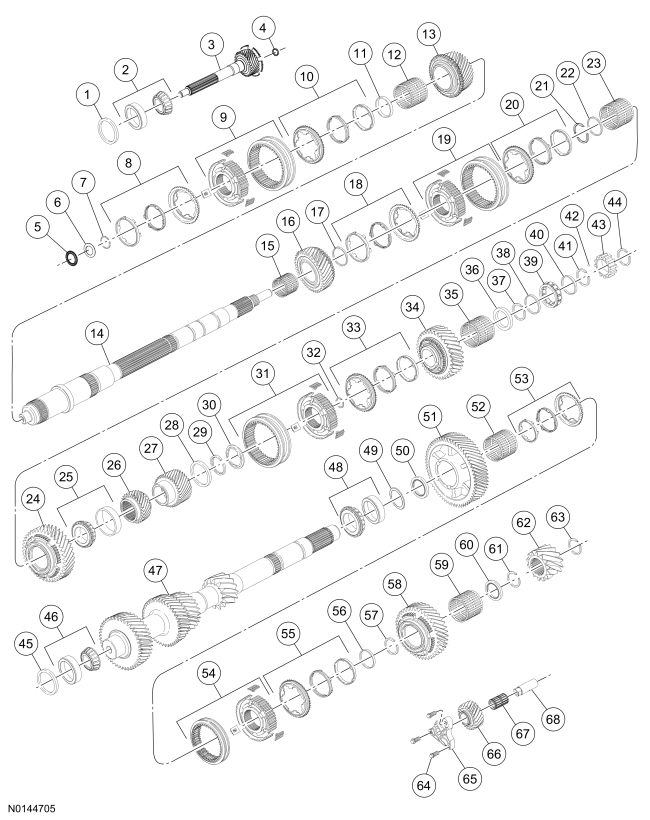
| 1 | 7L172 | Shim |
| 2 | 7025 | Input shaft bearing/race |
| 3 | 7017 | Input shaft |
| 4 | 7025 | Cylindrical roller bearing |
| 5 | 7025 | Axial thrust bearing |
| 6 | 7025 | Axial thrust washer |
| 7 | 7A082 | Snap ring |
| 8 | — | 4th gear synchronizer ring assembly |
| 9 | 7124 | 3rd/4th synchronizer assembly |
| 10 | 7107 | 3rd synchronizer ring assembly |
| 11 | 7117 | Spacer |
| 12 | 7M037 | 3rd gear needle bearing |
| 13 | 7B340 | 3rd gear |
| 14 | 7061 | Output shaft |
| 15 | 7M037 | 2nd gear needle bearing |
| 16 | 7102 | 2nd gear |
| 17 | 7117 | Spacer |
| 18 | 7107B | 2nd gear synchronizer ring assembly |
| 19 | 7124A | 1st/2nd synchronizer assembly |
| 20 | 7107A | 1st gear synchronizer ring assembly |
| 21 | 7A082A | Split ring |
| 22 | 7A082A | Retainer |
| 23 | 7025 | 1st gear needle bearing |
| 24 | 7100 | 1st gear |
| 25 | 7025 | Output shaft rear bearing/race |
| 26 | 7L047 | 6th driven gear |
| 27 | 7K316 | 5th driven gear |
| 28 | 7A082 | Retainer |
| 29 | 7A082 | Split ring |
| 30 | — | Synchronizer cone (part of 7107) |
| 31 | 7124B | Reverse synchronizer assembly |
| 32 | 7A082 | Snap ring |
| 33 | 7107C | Reverse gear synchronizer ring assembly |
| 34 | 7C238 | Reverse gear |
| 35 | 7025 | Reverse gear needle bearing |
| 36 | 7A385 | Thrust washer |
| 37 | 7A082 | Snap ring |
| 38 | 7A082 | Spacer |
| 39 | 7025 | Rear output shaft bearing |
| 40 | 7A082 | Spacer |
| 41 | 7A082 | Snap ring |
| 42 | 7E172 | Check ball |
| 43 | 7H150 | OSS sensor tone wheel |
| 44 | 7A082 | Snap ring |
| 45 | 7L172 | Shim |
| 46 | 7025 | Countershaft front bearing/race |
| 47 | 7113 | Countershaft |
| 48 | 7025 | Countershaft rear bearing/race |
| 49 | 7119 | Thrust washer |
| 50 | 7117 | Spacer |
| 51 | 7146 | 6th gear |
| 52 | 7025 | 6th gear needle bearing |
| 53 | 7107 | 6th gear synchronizer ring assembly |
| 54 | 7124 | 5th/6th synchronizer assembly |
| 55 | 7107 | 5th gear synchronizer ring assembly |
| 56 | 7117 | Spacer |
| 57 | 7A082 | Snap ring |
| 58 | 7144 | 5th gear |
| 59 | 7025 | 5th gear needle bearing |
| 60 | 7025 | Thrust washer |
| 61 | 7A082 | Snap ring |
| 62 | — | Reverse driver gear |
| 63 | 7A082 | Snap ring |
| 64 | 7C211 | Reverse idler shroud bracket bolt |
| 65 | 7723 | Reverse idler shaft bracket |
| 66 | 7141 | Reverse idler gear |
| 67 | 7025 | Reverse idler gear needle bearing |
| 68 | 7140 | Reverse idler gear shaft |
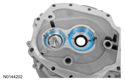
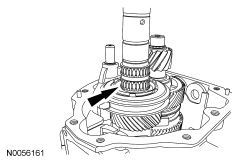
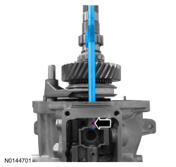
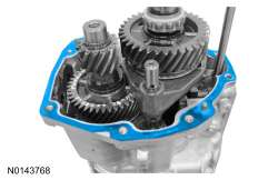
NOTE: If a new front input shaft bearing or front countershaft bearing was installed, install the new bearing cups.
Install the input shaft bearing cup and the countershaft bearing cup. Do not install the shims at this time.
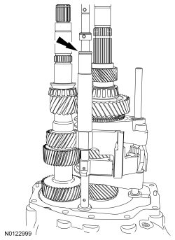
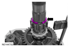
NOTICE: Make sure the countershaft seats into the oil pump drive or damage to the oil pump or transmission case can occur.
Align the oil pump drive with the countershaft and install the countershaft.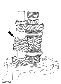
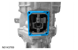
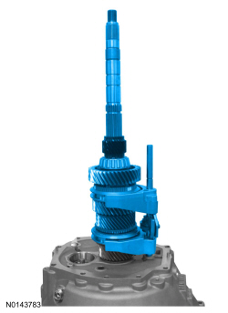
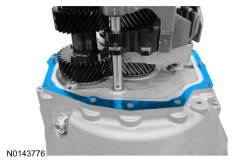
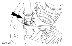
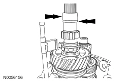
NOTICE: The input shaft/output shaft end play must be measured with a gasket installed between the clutch housing and the transmission main case or incorrect end play will occur.
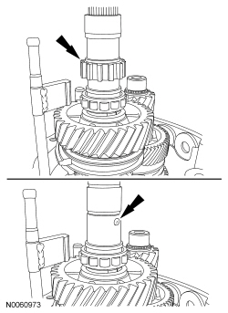
NOTE: Rotate the input shaft/output shaft to seat the bearings.
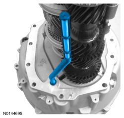
Using the Dial Indicator Gauge with Holding Fixture and the Clutch Housing Gauge, measure the input shaft/output shaft end play by applying an upward load on the input shaft. Record the measurement.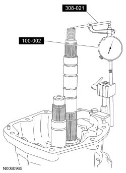
NOTICE: The countershaft shaft end play must be measured with a gasket installed between the clutch housing and the transmission main case or incorrect end play will occur.
NOTE: Rotate the countershaft to seat the bearings.
Using the Dial Indicator Gauge with Holding Fixture and the Clutch Housing Gauge, measure the countershaft gear end play by pulling upward on the countershaft. Record the measurement.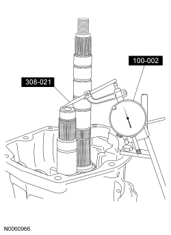

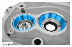
NOTICE: Make sure the countershaft seats into the oil pump drive or damage to the oil pump or transmission case can occur.
Align the oil pump drive with the countershaft and install the countershaft.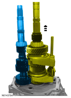
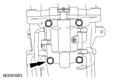
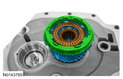
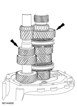
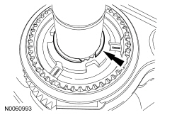
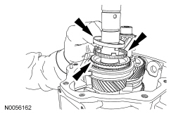
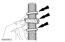
NOTE: Slide the synchronizer sleeve down while installing the pressure pieces.
Install the 5th/6th gear shift fork, the 5th/6th gear synchronizer sleeve and the 3 pressure pieces as an assembly.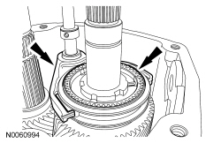
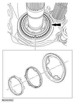
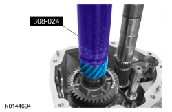
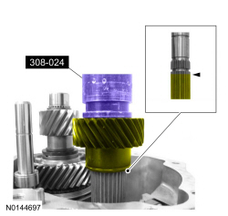
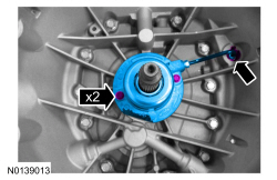
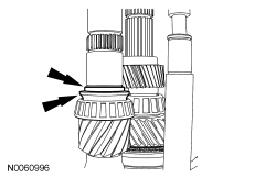
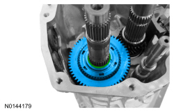
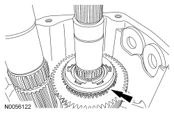
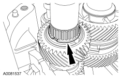
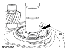
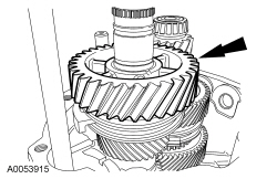
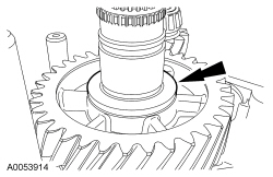
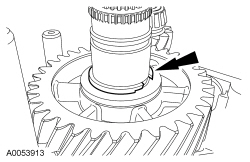
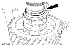
NOTE: Align the gear teeth of the 5th driven gear with the gear teeth of the 5th drive gear on the countershaft.
Using the Bearing Tube Remover/Installer, the Halfshaft Installer and the Transmission Extension Housing Bushing Installer, install the 5th driven gear in 2 stages: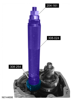
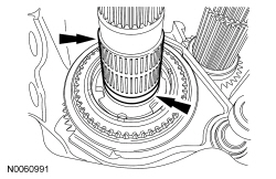
NOTE: Slide the synchronizer sleeve down while installing the pressure pieces.
Install the reverse shift fork, the reverse synchronizer sleeve and the 3 pressure pieces as an assembly.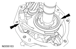
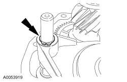
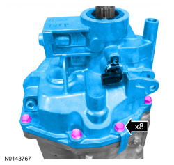
NOTE: Install the transmission identification tag in the location noted during removal.
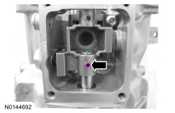
NOTE: Apply thread sealant to the threads of the 2 top extension housing bolts.
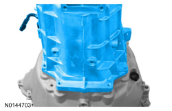
Install the extension housing and the 8 extension housing bolts.