SECTION 309-00: Exhaust System
| 2014 Mustang Workshop Manual
|
REMOVAL AND INSTALLATION
| Procedure revision date: 01/07/2013
|
Removal
NOTE: Exhaust fasteners are of a torque prevailing design. Use only new fasteners with the same part number as the original. Torque values must be used as specified during reassembly to make sure of correct retention of exhaust components.
NOTE: Discard the ball clamps and fasteners after removal.
All catalytic converters
RH catalytic converter
All catalytic converters
NOTICE: When repairing the exhaust system or removing exhaust components, disconnect the Catalyst Monitor Sensor (CMS) at the wiring connector to prevent damage to the sensor and wiring harness.
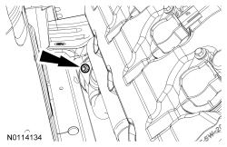
Disconnect the Catalyst Monitor Sensor (CMS) electrical connector.RH catalytic converter
LH catalytic converter
All catalytic converters
Installation
All catalytic converters
LH catalytic converter
NOTICE: Prior to installation, inspect the Catalyst Monitor Sensor (CMS) wiring harness for damage.
NOTE: Using a Scotch Brite® pad, clean the mating surfaces of the manifold outlet flare and the catalytic converter inlet flare, at the catalytic converter outlet flare and the exhaust H-pipe. Keep foreign materials out of the catalytic converters.
NOTE: Hand-tighten all the catalytic converter nuts.
Install the LH catalytic converter, gasket and 2 new nuts.RH catalytic converter
NOTICE: Prior to installation, inspect the Catalyst Monitor Sensor (CMS) wiring harness for damage.
NOTE: Using a Scotch Brite® pad, clean the mating surfaces of the manifold outlet flare and the catalytic converter inlet flare, at the catalytic converter outlet flare and the exhaust H-pipe. Keep foreign materials out of the catalytic converters.
NOTE: Hand-tighten all the catalytic converter nuts.
Install the RH catalytic converter, gasket and 2 new nuts.All catalytic converters
LH catalytic converter
NOTE: Tighten the LH catalytic converter-to-exhaust manifold nuts alternately in 10 Nm (89 lb-in) increments to maintain torque and draw flange evenly to assure alignment of exhaust system. Tighten the new nuts to 40 Nm (30 lb-ft).
NOTE: Make sure to correctly align the catalytic converter to the exhaust manifold and exhaust H-pipe before tightening the fasteners.
Tighten the 2 LH catalytic converter-to-exhaust manifold nuts.RH catalytic converter
NOTE: Tighten the RH catalytic converter-to-exhaust manifold nuts alternately in 10 Nm (89 lb-in) increments to maintain torque and draw flange evenly to assure alignment of exhaust system. Tighten the new nuts to 40 Nm (30 lb-ft).
NOTE: Make sure to correctly align the catalytic converter to the exhaust manifold and exhaust H-pipe before tightening the fasteners.
Tighten the 2 RH catalytic converter-to-exhaust manifold nuts.All catalytic converters