
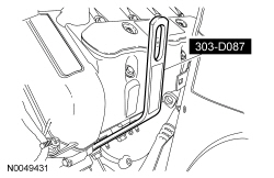
303-D087 (D93P-6001-A1)

303-F070

211-105 (T85M-3395-A)
SECTION 211-02: Power Steering
| 2014 Mustang Workshop Manual
|
REMOVAL AND INSTALLATION
| Procedure revision date: 01/07/2013
|
| Lifting Bracket, Engine
303-D087 (D93P-6001-A1) |
| Support Bar, Engine
303-F070 |
| Tie-Rod End Remover
211-105 (T85M-3395-A) |
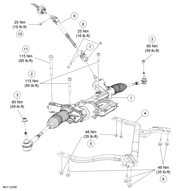
| Item | Part Number | Description |
|---|---|---|
| 1 | 3504 | Steering gear |
| 2 | W710909 | Steering gear bolts (2 required) |
| 3 | W705606 | Tie-rod end nuts (2 required) |
| 4 | 6C038 | Crossmember brace (if equipped) |
| 5 | W711553 | Crossmember brace nuts (if equipped) (2 required) |
| 6 | W714780 | Crossmember brace bolts (if equipped) (6 required) |
| 7 | — | Steering column shaft coupling (part of 3C662) |
| 8 | W704980 | Steering column shaft coupling bolts (2 required) |
| 9 | 3C662 | Lower steering column shaft |
| 10 | W704980 | Lower steering column shaft-to-upper steering column shaft bolt |
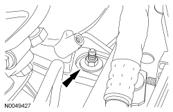
| 11 | W714406 | Steering gear bolt (1 required) |
Removal
All vehicles
Vehicles with 5.4L (4V) engine
NOTICE: Lift engine approximately 45 mm (1.771 in) from the bottom of the engine mount to the bottom of the engine bracket ensuring that no contact is made with the bulk head or damage to components may occur.
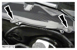
Install the Engine Support Bar.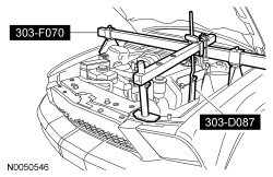
All vehicles
NOTICE: Do not allow the steering column to rotate while the steering column shaft is disconnected from the steering gear or damage to the clockspring may occur. If there is evidence that the steering column has rotated, the clockspring must be removed and recentered. For additional information, refer to Section 501-20B .
Remove the steering column shaft coupling-to-steering gear bolt.NOTE: Use a steering wheel holding device (such as Hunter® 28-75-1 or equivalent).
Using a suitable holding device, hold the steering wheel in the straight-ahead position.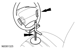
NOTE: The steering column shaft coupling will not be completely separated from the steering gear.
Slide the steering column shaft coupling upwards on the steering gear input shaft.NOTICE: Do not use a hammer to separate the outer tie-rod end from the wheel knuckle or damage to the wheel knuckle may result.
Using the Ball Joint Separator, separate the tie-rod ends from the wheel knuckles.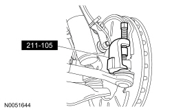

Vehicles with automatic transmission
All vehicles
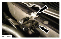
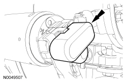
NOTICE: The ignition must be off when disconnecting Electronic Power Assist Steering (EPAS) electrical connectors. Failure to follow this direction may lead to DTCs being set in the EPAS module that can not be cleared, and result in the need to install a new EPAS assembly.
Release the 2 red Connector Position Assurance (CPA) features and disconnect the 2 Electronic Power Assist Steering (EPAS) electrical connectors.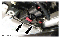
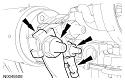
NOTE: If equipped with a 5.4L (4V) engine, it may be necessary to use a pry bar between the LH engine mount and engine bracket, pulling the engine forward slightly to remove LH steering gear bolt
Remove the 3 steering gear bolts and the steering gear.Installation
All vehicles
NOTICE: Do not allow the steering column to rotate while the steering column shaft is disconnected from the steering gear or damage to the clockspring may occur. If there is evidence that the steering column has rotated, the clockspring must be removed and recentered. For additional information, refer to Section 501-20B .
NOTE: Make sure the steering column coupling is aligned with the locator on the steering gear input shaft and the shaft is fully seated on the steering gear.
Position the steering gear, attach the steering column coupling and install the 3 steering gear bolts.NOTE: Make sure the Electronic Power Assist Steering (EPAS) electrical connectors are fully seated and the Connector Position Assurance (CPA) features are engaged.
Connect the 2 Electronic Power Assist Steering (EPAS) electrical connectors and secure the 2 red Connector Position Assurance (CPA) features.Vehicles with automatic transmission
All vehicles
Vehicles with 5.4L (4V) engine
NOTE: While lowering the engine, make sure that the engine bracket aligns to the engine mount stud bolt. If necessary, shift the engine slightly when lowering.
Using the Engine Lifting Bracket and Engine Support Bar, lower the LH side of the engine onto the engine mount.All vehicles