
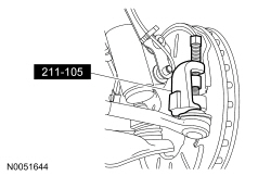
211-105 (T85M-3395-A)
SECTION 211-02: Power Steering
| 2014 Mustang Workshop Manual
|
REMOVAL AND INSTALLATION
| Procedure revision date: 01/07/2013
|
| Tie-Rod End Remover
211-105 (T85M-3395-A) |
| Item | Specification |
|---|---|
| Premium Long-Life Grease
XG-1-C or XG-1-K (US); CXG-1-C (Canada) | ESA-M1C75-B |
| Threadlock 262
TA-26 | WSK-M2G351-A6 |
NOTE: LH side shown, RH similar.
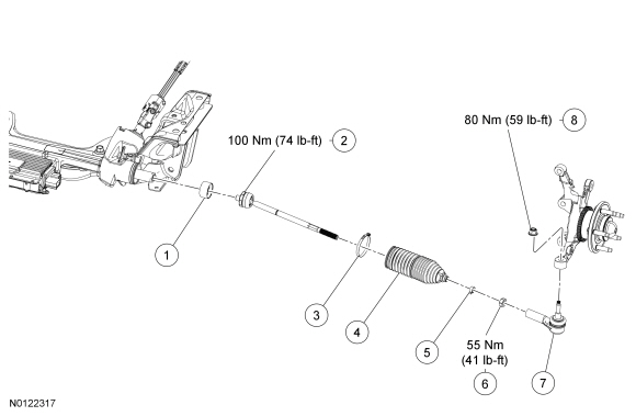
| Item | Part Number | Description |
|---|---|---|
| 1 | — | Steering stop (part of 3280 tie rod kit) |
| 2 | — | Inner tie rod (part of 3280 tie rod kit) |
| 3 | — | Inner bellows boot clamp (part of 3280 tie rod kit or 3K661 boot kit) |
| 4 | — | Steering gear bellows boot (part of 3280 tie rod kit or 3K661 boot kit) |
| 5 | — | Outer bellows boot clamp (part of 3280 tie rod kit or 3K661 boot kit) |
| 6 | W713882 | Tie-rod jam nut |
| 7 | 3A130 | Outer tie-rod end |
| 8 | W705606 | Outer tie-rod end nut |
Removal
NOTICE: The steering gear bellows boots and clamps are designed to provide an airtight seal and protect the internal components of the steering gear. If the seal is not airtight, the vacuum generated during turning will draw water and foreign material into the gear causing damage. Zip ties do not produce an airtight seal and must not be used.
NOTICE: The inner tie-rod ball joint grease is not compatible with water. Water trapped in the grease may damage the joint.
NOTICE: Disconnect the Electronic Power Assist Steering (EPAS) steering gear power supply electrical connector or damage to the steering gear internal power relay may occur resulting in steering gear replacement.
NOTICE: The ignition must be off when disconnecting Electronic Power Assist Steering (EPAS) electrical connectors. Failure to follow this direction may lead to DTCs being set in the EPAS module that can not be cleared, and result in the need to install a new EPAS assembly.
Release the red Connector Position Assurance (CPA) feature and disconnect the Electronic Power Assist Steering (EPAS) power supply electrical connector.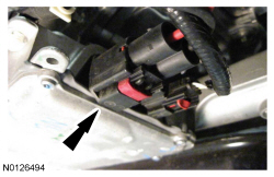
NOTE: Count the number of turns required to remove the tie-rod end for reference during installation.
Remove the outer tie-rod ends.NOTE: Install new bellows boot clamps.
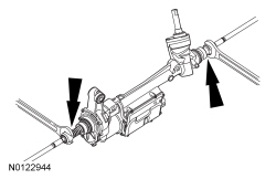
Remove and discard the 2 inner and 2 outer bellows boot clamps.NOTE: Note the orientation of the steering stops for reference during installation.
Place a open end wrench against the outboard edge of the steering stops and tap the wrench with a hammer to separate the steering stops from the inner tie rods.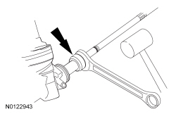
Installation
NOTICE: Install the steering stops using hand force only. Striking the steering stops may cause damage to the stops.
NOTE: An audible click will be heard when the steering stop seats onto the inner tie rod. Make sure that the steering stops are fully seated and cannot be separated by hand.
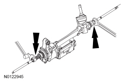
Install the steering stops onto the inner tie rods using hand force only.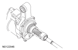
NOTE: Make sure the steering gear bellows boot is positioned correctly over the steering gear housing bead and the groove in the inner tie rod.
Install the 2 steering gear bellows boots.NOTE: Make sure the end of the steering gear bellows is positioned between the 2 grooves on the inner tie rod or an internal leak can result.
Install a 2 new outer bellows boot clamps.NOTE: Install the tie-rod end the same number of turns as recorded during the removal.
Install the outer tie-rod ends on the inner tie rods.NOTE: Make sure the Electronic Power Assist Steering (EPAS) electrical connector is fully seated and the Connector Position Assurance (CPA) feature is engaged.
Connect the Electronic Power Assist Steering (EPAS) power supply electrical connector and secure the red Connector Position Assurance (CPA) feature.