SECTION 412-01: Climate Control
| 2014 Mustang Workshop Manual
|
DESCRIPTION AND OPERATION
| Procedure revision date: 01/07/2013
|
The A/C system components are:
The refrigerant system incorporates an A/C compressor controlled by the PCM through an A/C clutch relay.
An A/C compressor pressure relief valve is installed in the A/C compressor to protect the refrigerant system against excessively high refrigerant pressures.
Refrigerant flow into the evaporator core is metered by a TXV .
For information concerning the refrigerant cycle and principles of A/C operation, refer to Section 412-00 .
A/C Compressor and Clutch Assembly
NOTE: Internal A/C compressor components are not serviced separately. The A/C compressor is serviced only as an assembly. The clutch disc and hub, A/C compressor pulley and bearing and clutch field coil are serviceable.
The A/C compressor:
Use standard oil matching procedures when installing new compressors.
The magnetic A/C clutch has the following characteristics:
Thermostatic Expansion Valve (TXV)
The TXV is located at the evaporator core inlet and outlet tubes at the center rear of the engine compartment. The TXV provides a restriction to the flow of refrigerant from the high-pressure side of the refrigerant system and separates the low-pressure and high-pressure sides of the refrigerant system. Refrigerant entering and exiting the evaporator core passes through the TXV through 2 separate flow paths. An internal temperature sensing bulb senses the temperature of the refrigerant flowing out of the evaporator core and adjusts an internal pin-type valve to meter the refrigerant flow into the evaporator core. The internal pin-type valve decreases the amount of refrigerant entering the evaporator core at lower temperatures and increases the amount of refrigerant entering the evaporator core at higher temperatures.
A/C Evaporator Discharge Air Temperature Sensor
The evaporator discharge air temperature sensor contains a thermistor. The resistance of this thermistor varies by a specific amount based on the evaporator discharge air temperature. The HVAC module measures a voltage ratio between the reference voltage it supplies to the sensor and the sensor voltage to determine this resistance and the associated discharge air temperature.
The evaporator discharge air temperature sensor maintains evaporator core temperature and prevents icing of the evaporator core. The temperature information from the sensor is used by the HVAC module to switch off the A/C request signal to the Instrument Cluster (IC) when the evaporator discharge air temperature falls below approximately 7°C (45°F). The A/C request will be switched back on when the evaporator discharge air temperature rises above acceptable levels.
The A/C evaporator discharge air temperature sensor is located on the heater core and evaporator core housing to the right of the accelerator pedal.
A/C Pressure Transducer
NOTE: It is not necessary to recover the refrigerant before removing the A/C pressure transducer.
The A/C pressure transducer monitors the compressor discharge pressure and sends a variable voltage signal representing the pressure to the PCM. The PCM will interrupt A/C compressor operation in the event that the A/C pressure transducer indicates high system discharge pressures. It is also used to sense low charge conditions. If the pressure is below a predetermined value for a given ambient temperature, the PCM will not allow the clutch to engage.
The A/C pressure transducer is located on the compressor-to-condenser discharge line near the condenser inlet fitting.
Condenser Core
The condenser is an aluminum fin and tube design heat exchanger, located in front of the vehicle radiator. It cools compressed refrigerant gas by allowing air to pass over fins and tubes to extract heat, and by condensing gas to liquid refrigerant as it is cooled.
Evaporator Core
NOTE: The evaporator core is not individually serviced. It is serviced only with the heater core and evaporator core housing.
The evaporator core is an aluminum plate/fin type and is located in the heater core and evaporator core housing. A mixture of liquid refrigerant and oil enters the bottom of the evaporator core through the evaporator core inlet tube and then moves out of the evaporator core through the evaporator core outlet tube as a vapor. Air from the blower motor is cooled and dehumidified as it flows through the evaporator core fins.
The evaporator core is located in the heater core and evaporator core housing.
Receiver/Drier
NOTE: Installation of a new receiver/drier is not required when repairing the A/C system, except when there is physical evidence of contamination from a failed A/C compressor or damage to the receiver/drier. Damage to the receiver/drier includes leaks, physical damage to the receiver/drier shell or desiccant, or moisture contamination. Moisture contamination results only from a complete loss of refrigerant, and equalization of the refrigerant system pressure with atmospheric pressure for a period longer than one hour. If even a slight amount of positive refrigerant pressure is present in the refrigerant system before repairs are carried out, a new receiver/drier should not be installed.
The receiver/drier is mounted to the LH front of the condenser core. It stores high-pressure liquid after it leaves the condenser core. A desiccant cartridge mounted inside the receiver/drier removes moisture from the refrigerant.
A/C Compressor Pressure Relief Valve
NOTE: If the A/C compressor is operating within limits and the A/C pressure relief valve is venting, or if the A/C pressure relief valve is leaking around the threads, install a new A/C pressure relief valve and O-ring. If the A/C pressure relief valve still vents after it is replaced, diagnose the refrigerant system for a restriction.
An A/C pressure relief valve is incorporated in the A/C compressor, as a redundant backup to the A/C pressure transducer, to prevent damage to the A/C compressor and other system components by relieving unusually high system discharge pressure buildups. Under normal conditions the A/C pressure relief valve will never vent. Only a failure of the A/C pressure relief valve, A/C pressure transducer or A/C clutch control system, overheating of the refrigerant system, or a restriction in the refrigerant system between the A/C compressor and A/C pressure transducer will cause the A/C pressure relief valve to vent.
The A/C pressure relief valve is a separate component and can be replaced separately from the A/C compressor. It is necessary to recover the refrigerant before removing the A/C pressure relief valve.
Service Gauge Port Valves
The high-pressure service gauge port valve is located on the condenser-to-evaporator line.
The low-pressure service gauge port valve is located on the A/C compressor suction line.
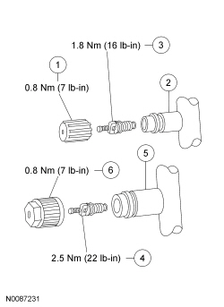
| Item | Part Number | Description |
|---|---|---|
| 1 | 19D702 | Low-pressure service gauge port valve cap |
| 2 | — | Low-pressure service gauge port valve |
| 3 | 19D701 | Low-pressure Schrader-type valve |
| 4 | 19D701 | High-pressure Schrader-type valve |
| 5 | — | High-pressure service gauge port valve |
| 6 | 19D702 | High-pressure service gauge port valve cap |
The fitting is an integral part of the refrigerant system line or component.
Refrigerant System Dye
Fluorescent refrigerant system dye is added to the refrigerant system at the factory to assist in refrigerant system leak diagnosis using a Rotunda-approved ultraviolet blacklight. It is not necessary to add additional dye to the refrigerant system before diagnosing leaks, even if a significant amount of refrigerant has been removed from the system. New receiver/driers are shipped with a fluorescent dye "wafer" included in the desiccant bag which will dissolve after approximately 30 minutes of continued A/C operation. It is not necessary to add dye after flushing or filtering the refrigerant system because a new receiver/drier is installed as part of the flushing or filtering procedure. Additional refrigerant system dye should only be added if more than 50% of the refrigerant system lubricant capacity has been lost due to a fitting separation, hose rupture or other damage. Refer to Section 412-00 .