SECTION 413-01: Instrumentation, Message Center, and Warning Chimes
| 2014 Mustang Workshop Manual
|
DESCRIPTION AND OPERATION
| Procedure revision date: 01/07/2013
|

| Item | Part Number | Description |
|---|---|---|
| 1 | — | Safety belt warning indicator |
| 2 | — | Grade assist indicator |
| 3 | — | Speedometer |
| 4 | — | Low fuel warning indicator |
| 5 | — | LH turn indicator |
| 6 | — | Fuel gauge |
| 7 | — | Brake warning indicator |
| 8 | — | Engine temperature gauge |
| 9 | — | RH turn indicator |
| 10 | — | Engine over temperature warning indicator |
| 11 | — | Anti-theft indicator |
| 12 | — | Tachometer |
| 13 | — | Message center display area |
| 14 | — | Powertrain malfunction (wrench) indicator |
| 15 | — | Low oil pressure warning indicator |
| 16 | — | Charging system warning indicator |
| 17 | — | Stability/traction control indicator (sliding car icon) |
| 18 | — | Cruise control indicator |
| 19 | — | Door ajar warning indicator |
| 20 | — | ABS warning indicator |
| 21 | — | Stability/traction control disabled indicator (sliding car OFF icon) |
| 22 | — | Malfunction Indicator Lamp (MIL) |
| 23 | — | Tire Pressure Monitoring System (TPMS) warning indicator |
| 24 | — | High beam indicator |
| 25 | — | Airbag warning indicator |

| Item | Part Number | Description |
|---|---|---|
| 1 | — | Safety belt warning indicator |
| 2 | — | Grade assist indicator |
| 3 | — | High beam indicator |
| 4 | — | Speedometer |
| 5 | — | ABS warning indicator |
| 6 | — | Cruise control indicator |
| 7 | — | Stability/traction control indicator (sliding car icon) |
| 8 | — | Odometer |
| 9 | — | Main display area/message center display |
| 10 | — | Select shift display (if equipped) |
| 11 | — | Message center indicator display area |
| 12 | — | Low oil pressure warning indicator |
| 13 | — | Anti-theft indicator |
| 14 | — | Tachometer |
| 15 | — | Fuel gauge |
| 16 | — | Engine temperature gauge |
| 17 | — | Charging system warning indicator |
| 18 | — | RH turn indicator |
| 19 | — | Brake warning indicator |
| 20 | — | LH turn indicator |
| 21 | — | Low fuel warning indicator |
| 22 | — | Door ajar warning indicator |
| 23 | — | Stability/traction control disabled indicator (sliding car OFF icon) |
| 24 | — | MIL |
| 25 | — | TPMS warning indicator |
| 26 | — | Airbag warning indicator |

| Item | Part Number | Description |
|---|---|---|
| 1 | — | Safety belt warning indicator |
| 2 | — | Upshift indicator |
| 3 | — | High beam indicator |
| 4 | — | Speedometer |
| 5 | — | ABS warning indicator |
| 6 | — | Cruise control indicator |
| 7 | — | Stability/traction control indicator (sliding car icon) |
| 8 | — | Odometer |
| 9 | — | Main display area/message center display |
| 10 | — | Message center indicator display area |
| 11 | — | Low oil pressure warning indicator |
| 12 | — | Anti-theft indicator |
| 13 | — | Tachometer |
| 14 | — | SVT performance shift indicator |
| 15 | — | Fuel gauge |
| 16 | — | Engine temperature gauge |
| 17 | — | Charging system warning indicator |
| 18 | — | RH turn indicator |
| 19 | — | Brake warning indicator |
| 20 | — | LH turn indicator |
| 21 | — | Low fuel warning indicator |
| 22 | — | Door ajar warning indicator |
| 23 | — | Stability/traction control disabled indicator (sliding car OFF icon) |
| 24 | — | MIL |
| 25 | — | TPMS warning indicator |
| 26 | — | Airbag warning indicator |
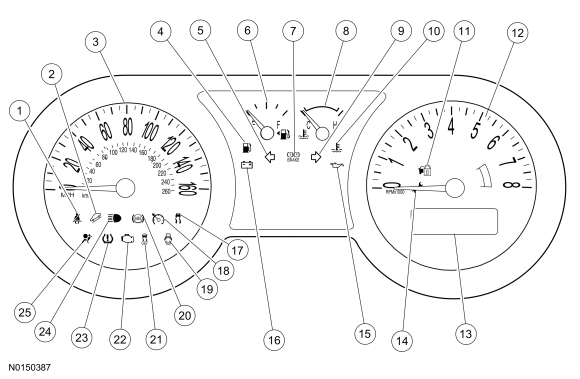
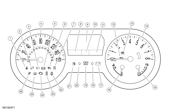
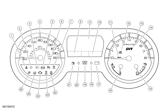
The Instrument Panel Cluster (IPC) contains gauges, informational indicators, warning indicators, warning chimes and a message center designed to provide the driver with system status and to alert the driver that certain conditions exist in the vehicle.
There are 2 basic IPC configurations, base 2x14 line message center and the optional LCD message center. The optional LCD message center IPC has 2 different variations based on vehicle line (optional and GT500).
MyKey®
The MyKey® feature allows the customer to program a restricted driving mode that is tied to one or more keys known as a MyKey®. When a MyKey® is in use, the IPC provides the following functions:
When an administrator key is in use, the IPC provides the following functions:
Refer to Owner's Literature for additional information on the MyKey® features.
Gauges
Gauges provide information to the driver indicating the status of systems. There are 2 types of gauges used, analog and virtual. Analog gauges are fixed gauges and use actual pointers to provide indication. Virtual gauges are displayed in the LCD display area and are images of gauges that use virtual pointers.
Informational Indicators
Informational indicators provide information to the driver of conditions that exist in the vehicle. The informational indicators are:
Warning Indicators
Warning indicators provide information to the driver of conditions that could potentially cause personal injury or alter vehicle performance. The warning indicators are:
Hardwired Inputs
The hardwired inputs are provided from the following systems or components:
Network Messaged Inputs
Module messaging is becoming the standard for sending and receiving information required to operate the IPC . For a complete list of module messages with the message origination sources, refer to Section 418-00 .
The status and information messages that the IPC requires from other vehicle inputs are grouped into the following systems/subsystems: