SECTION 414-01: Battery, Mounting and Cables
| 2014 Mustang Workshop Manual
|
REMOVAL AND INSTALLATION
| Procedure revision date: 01/07/2013
|
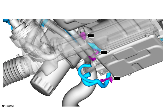
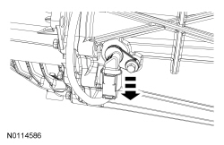
NOTE: Automatic transmission shown, manual transmission similar. Some items have been removed for clarity.
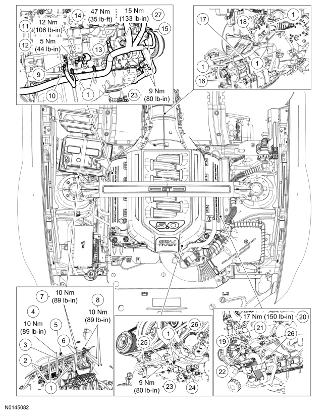
| Item | Part Number | Description |
|---|---|---|
| 1 | — | Battery cable harness locator (part of 14300) |
| 2 | — | PCM harness connector (part of 14300) |
| 3 | — | Battery Junction Box (BJB) terminal (part of 14300) |
| 4 | W705764 | BJB terminal nut |
| 5 | — | Engine control harness connector (part of 14300) |
| 6 | — | Battery ground cable body terminal (part of 14300) |
| 7 | W712583 | Battery ground cable body terminal bolt |
| 8 | W705764 | Battery cable terminal nut |
| 9 | — | Starter solenoid positive cable terminal (part of 14300) |
| 10 | — | Starter solenoid wire terminal (part of 14300) |
| 11 | W706414 | Starter solenoid positive cable terminal nut |
| 12 | W705790 | Starter solenoid wire terminal nut |
| 13 | — | Battery ground cable-to-engine terminal (part of 14300) |
| 14 | W520103 | Battery ground cable-to-engine terminal nut |
| 15 | — | A/C compressor connector (part of 14300) |
| 16 | — | Transmission vehicle harness connector (part of 14300) |
| 17 | — | Catalyst Monitor Sensor (CMS) connector (part of 14300) |
| 18 | — | Upper Heated Oxygen Sensor (HO2S) connector (part of 14300) |
| 19 | — | Generator B+ terminal (part of 14300) |
| 20 | W711953 | Generator B+ terminal nut |
| 21 | — | Generator B+ terminal cover (part of 14300) |
| 22 | — | Generator connector (part of 14300) |
| 23 | W705790 | Battery cable harness bracket nut |
| 24 | — | Electronic Power Assist Steering (EPAS) connector (part of 14300) |
| 25 | — | Battery cable harness bracket (part of 14300) |
| 26 | — | Battery cable harness locator (part of 14300) (vehicles equipped with an oil cooler) |
| 27 | W506033 | Battery cable harness bracket bolt |
All vehicles
Automatic transmission
Manual transmission
All vehicles