SECTION 414-01: Battery, Mounting and Cables
| 2014 Mustang Workshop Manual
|
REMOVAL AND INSTALLATION
| Procedure revision date: 01/07/2013
|
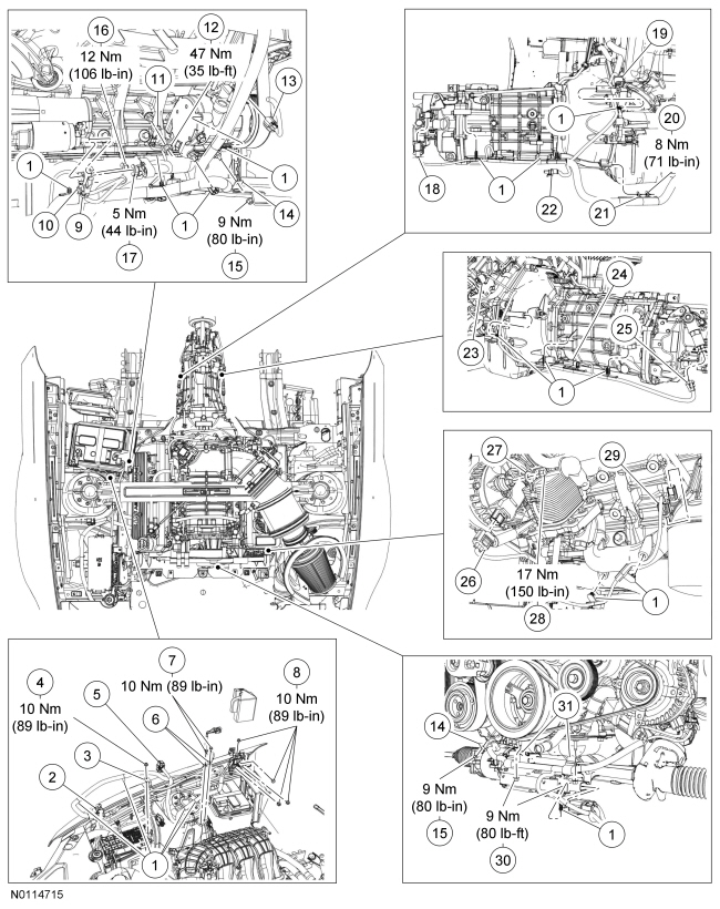
| Item | Part Number | Description |
|---|---|---|
| 1 | — | Battery cable harness locator (part of 14B060) |
| 2 | — | PCM harness connector (part of 14B060) |
| 3 | — | Battery Junction Box (BJB) terminal (part of 14B060) |
| 4 | W705764 | BJB terminal nut |
| 5 | — | Engine control harness connector (part of 14B060) |
| 6 | — | Battery ground cable body terminal (part of 14B060) |
| 7 | W712583 | Battery ground cable body terminal bolt (2 required) |
| 8 | W705764 | Battery cable terminal nut (4 required) |
| 9 | — | Starter solenoid positive cable terminal (part of 14B060) |
| 10 | — | Starter solenoid wire terminal (part of 14B060) |
| 11 | — | Battery ground cable-to-engine terminal (part of 14B060) |
| 12 | W520103 | Battery ground cable-to-engine terminal nut |
| 13 | — | A/C compressor connector (part of 14B060) |
| 14 | — | Battery cable harness bracket (part of 14B060) |
| 15 | W705790 | Battery cable harness bracket nut |
| 16 | W706414 | Starter solenoid positive cable terminal nut |
| 17 | W705790 | Starter solenoid wire terminal nut |
| 18 | — | Output Shaft Speed (OSS) connector (part of 14B060) |
| 19 | — | Right upper Heated Oxygen Sensor (HO2S) connector (part of 14B060) |
| 20 | W701014 | Lower battery cable harness bracket nut |
| 21 | — | Lower battery cable harness bracket (part of 14B060) |
| 22 | — | Reverse switch connector (part of 14B060) |
| 23 | — | Left upper Heated Oxygen Sensor (HO2S) connector (part of 14B060) |
| 24 | — | Left lower Heated Oxygen Sensor (HO2S) connector (part of 14B060) |
| 25 | — | Reverse lockout solenoid connector (part of 14B060) |
| 26 | — | Generator connector (part of 14B060) |
| 27 | — | Generator B+ terminal (part of 14B060) |
| 28 | W711953 | Generator B+ terminal nut |
| 29 | — | Oil pressure switch connector (part of 14B060) |
| 30 | W705790 | Battery cable harness bracket nut |
| 31 | — | Battery cable harness bracket (part of 14B060) |
| 32 | — | Electronic Power Assist Steering (EPAS) connector (part of 14B060) |
Removal and Installation