SECTION 419-01A: Anti-Theft — Perimeter
| 2014 Mustang Workshop Manual
|
REMOVAL AND INSTALLATION
| Procedure revision date: 01/07/2013
|

| Item | Part Number | Description |
|---|---|---|
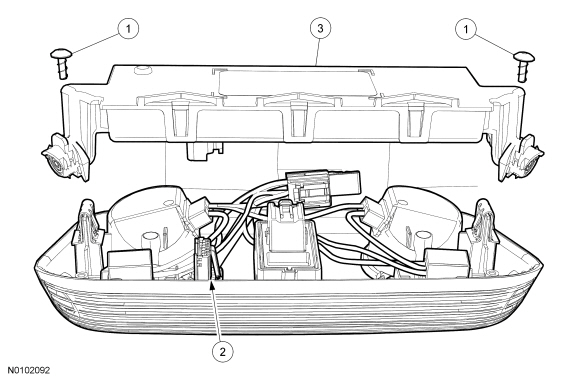
| 1 | — | Intrusion and inclination sensor screws (2 required) |
| 2 | — | Overhead console jumper harness electrical connector (part of 10503) |
| 3 | 15K609 | Intrusion and inclination sensor |
Removal
NOTE: Prior to the removal of the intrusion and inclination sensor, it is necessary to upload the Body Control Module B (BCM-B) configuration information to the scan tool. This information must be downloaded back into the same BCM-B after installation of a new intrusion and inclination sensor in order to establish the correct configuration of the BCM-B into the new intrusion and inclination sensor. For additional information, refer to Section 418-01 .
NOTE: If the intrusion and inclination sensor is being replaced, follow this step. If the intrusion and inclination sensor is not being replaced, proceed to Step 2.
Upload the module configuration information from the BCM-B and the scan tool. For additional information, refer to Section 418-01 .Installation
NOTE: The correct Integrated Diagnostic System (IDS) selections are SELF-TEST — MODULES — BCM-B and SELF-TEST — MODULES — SJB. If the IDS selections SELF-TEST — MODULES — BODY — SECURITY — PERIMETER are used, only the Smart Junction Box (SJB) is self-tested.
Carry out the self-test (must include an on-demand self-test) for the SJB and also for the BCM-B . Clear the DTCs in both modules and then retrieve the DTCs from both modules to confirm all DTCs (in both modules) have been cleared.