SECTION 419-10: Multifunction Electronic Modules
| 2014 Mustang Workshop Manual
|
REMOVAL AND INSTALLATION
| Procedure revision date: 01/07/2013
|
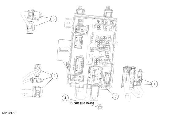
| Item | Part Number | Description |
|---|---|---|
| 1 | — | Smart Junction Box (SJB) Electrical connectors (part of 14A005) (2 required) |
| 2 | — | SJB Electrical connectors (part of 14290) (3 required) |
| 3 | — | SJB Electrical connectors (part of 14401) (2 required) |
| 4 | W706287-S | SJB nut |
| 5 | 14B476 | SJB |
Removal
NOTICE: Electronic modules are sensitive to static electrical charges. If exposed to these charges, damage to the module may result.
NOTE: Prior to the replacement of the module, it is necessary to upload the module configuration information to a scan tool. This information must be downloaded into the new Smart Junction Box (SJB) after installation. For additional information, refer to Section 418-01 to carry out Programmable Module Installation (PMI).
NOTE: The Tire Pressure Monitoring System (TPMS) functionality is integral to the SJB .
NOTE: A new SJB is delivered in a "manufacturing mode" with 8 pre-set DTCs. A successful configuration of the SJB , then a successful TPMS sensor training, then a successful self-test including the clearing of all DTCs is required in order to clear the 8 pre-set manufacturing mode DTCs. The 8 manufacturing mode DTCs are:
NOTE: This step is only necessary if the SJB is being replaced.
Upload the module configuration information from the SJB into the scan tool. For additional information, refer to Section 418-01 .NOTE: It may be necessary to push the red lock tab downward and press the 2 black tangs inward to release the B+ connector.
Disconnect the 7 electrical connectors.Installation
NOTE: It may be necessary to push the red lock tab upward after installing the B+ connector.
Connect the 7 SJB electrical connectors.NOTE: If the SJB is not being replaced, this is the last step that is necessary.
Install the RH A-pillar lower trim panel.NOTE: DTC B2276 may be set, indicating there are less than 2 transmitters programmed to the SJB . For additional information, refer to Section 501-14 .
Download the SJB configuration information from the scan tool to the SJB . For additional information, refer to Section 418-01 .NOTE: The SJB DTC C2780 will not clear if any other DTCs are still present in the SJB .
NOTE: This step is required to clear the SJB DTC C2780, allow the SJB to exit the manufacturing mode, and to make sure there are no other concerns with the newly programmed SJB .
Carry out the SJB self-test (must include an on-demand self-test) and then repeat the self-test to confirm all SJB DTCs have been cleared.