SECTION 501-09: Rear View Mirrors
2014 Mustang Workshop Manual
DIAGNOSIS AND TESTING
Procedure revision date: 01/07/2013

Rear View Mirrors — Exterior


Special Tool(s)
Fluke 77-IV Digital Multimeter
FLU77-4 or equivalent
 

Principles of Operation

Exterior Rear View Mirrors

The movement of the LH and RH exterior mirror glass is controlled by the exterior mirror control switch and the LH and RH exterior mirror motors. Adjusting the exterior mirror switch to the LH or RH position determines which exterior mirror motor will be controlled. When the exterior mirror control switch is adjusted to the left, right, up or down position, the exterior mirror control switch will supply voltage and ground to the selected exterior mirror motor to move the exterior mirror glass to the desired position.

The exterior mirrors use a jumper harness between the vehicle wire harness connector and the exterior mirror motor. The exterior mirror jumper harness is integral to the exterior mirror. If a concern with the exterior mirror jumper harness exists and cannot be repaired, a new exterior mirror must be installed.

Pony Projection Lamps

The LH and RH exterior mirrors may be equipped with Pony Projection Lamps, which illuminate when the interior lights are turned on by opening a door or pressing the unlock button on the RKE transmitter. For repair procedures and information, refer to Section 417-02 .

Heated Exterior Mirrors

The rear window defrost switch controls the operation of the heated exterior mirror glass. The heated exterior mirror glass only operates when the rear window defrost system is ON. Voltage is supplied to the heated exterior mirror glass by the rear defrost relay, through Battery Junction Box (BJB) fuse 39 (10A), which isolates the rear window defrost system from the heated exterior mirror system in the event of a concern.


Inspection and Verification

  1. Clean the entire mirror assembly and glass to assist in verification of the customer concern and/or impact damage.

    NOTE: Do not clean the mirror glass with an ice scraper, razor blade, abrasive pad or harsh chemicals, as these may damage the glass and/or housing.

  1. Visually inspect for obvious signs of mechanical or electrical damage.

      Visual Inspection Chart

    Mechanical Electrical
    • Exterior mirror
    • Exterior mirror cover
    • BJB fuse 39 (10A)
    • Smart Junction Box (SJB) fuse 12 (7.5A)
    • SJB
    • Exterior mirror control switch
    • Exterior mirror motor
    • Exterior mirror
    • Loose or corroded connections
    • Wiring harness

  1. If the concern is not visually evident, verify the symptom and GO to Symptom Chart - Rear View Mirrors or GO to Symptom Chart - NVH .
 

Symptom Chart(s)

Diagnostics in this manual assume a certain skill level and knowledge of Ford-specific diagnostic practices. REFER to Diagnostic Methods in Section 100-00 for more information about these practices.

 
Symptom Chart — Rear View Mirrors
Condition Possible Sources Action
  • Both mirrors are inoperative
  • Fuse
  • Wiring, terminals or connectors
  • Exterior mirror control switch
  • A single mirror is inoperative
  • Wiring, terminals or connectors
  • Exterior mirror control switch
  • Exterior mirror motor
  • Exterior mirror
  • A single mirror does not operate correctly
  • Wiring, terminals or connectors
  • Exterior mirror control switch
  • Exterior mirror motor
  • Exterior mirror
  • The heated exterior mirror is inoperative
  • Fuse
  • Wiring, terminals or connectors
  • Exterior mirror glass
  • Exterior mirror
  • Rear window defrost system concern
  • The Pony Projection Lamp is inoperative
  • Fuse
  • SJB
  • Wiring, terminals or connectors
  • Exterior mirror
 
Symptom Chart — NVH

NOTE: NVH symptoms should be identified using the diagnostic tools that are available. For a list of these tools, an explanation of their uses and a glossary of common terms, refer to Section 100-04 . Since it is possible any one of multiple systems may be the cause of a symptom, it may be necessary to use a process of elimination type of diagnostic approach to pinpoint the responsible system. If this is not the causal system for the symptom, refer back to Section 100-04 for the next likely system and continue diagnosis.

Condition Possible Sources Action
  • Mirror vibrates/loose
  • Exterior mirror mounting nuts loose
  • TIGHTEN the mounting nuts to the specified value in the Specifications table.
    • Mirror glass loose
    • COMPARE the LH and RH exterior mirror glass to verify that the exterior mirror glass is loose. PRESS the center of the exterior mirror glass up, down, left and right to make sure that the exterior mirror glass is seated correctly. If the exterior mirror glass is still loose, REMOVE the exterior mirror glass and INSPECT the exterior mirror backing plate for damage. If the exterior mirror backing plate is damaged, INSTALL a new exterior mirror glass. REFER to Exterior Mirror Glass .
      • Aftermarket air deflector/stone shields
      • If possible, REMOVE aftermarket air deflector/stone shield, then ROAD TEST the vehicle. If concern is no longer present, ADVISE customer that aftermarket components were causing undesired vibration.
        • Impact damage to pivot and/or housing
          • Mirror motor mounting screws loose
          • REMOVE the exterior mirror glass and inspect the motor mounting screws. TIGHTEN the screws if needed. INSTALL the exterior mirror glass. REFER to Exterior Mirror Glass .
          • Wind noise
          • Foam gasket between the rear view mirror and door is missing or damaged
          • VERIFY gasket is present and in good condition. REPOSITION gasket or INSTALL a new foam gasket between rear view mirror and door frame if necessary.
            • Exterior mirror is not correctly fitted to the door
            • VERIFY that there are no gaps between the exterior mirror and the door. If necessary, LOOSEN the exterior mirror nuts and REPOSITION the exterior mirror.
              • Exterior mirror cover is loose
              • VERIFY the exterior mirror cover is not loose or broken. If necessary, INSTALL a new exterior mirror cover. REFER to Exterior Mirror Cover .
               

              Pinpoint Tests


              Pinpoint Test A: Both Mirrors are Inoperative

              Diagnostic Overview

              Diagnostics in this manual assume a certain skill level and knowledge of Ford-specific diagnostic practices. REFER to Diagnostic Methods in Section 100-00 for more information about these practices.

              Refer to Wiring Diagrams Cell 124 , Power Mirrors for schematic and connector information.

              Normal Operation

              The exterior mirror control switch receives power from the Smart Junction Box (SJB) through circuit SBP12(GN/RD) and ground through circuit GD133(BK). The exterior mirror control switch uses circuit CPM23(GY) as the common circuit for both exterior mirror up/down and right/left movement.

               
              PINPOINT TEST A: BOTH MIRRORS ARE INOPERATIVE
              Test Step Result / Action to Take
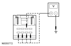
                A1 CHECK FOR VOLTAGE TO EXTERIOR MIRROR CONTROL SWITCH  
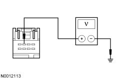
              • Ignition OFF.
              • Disconnect: Exterior Mirror Control Switch C527.
              • Ignition ON.
              • Measure the voltage between exterior mirror control switch C527-3, circuit SBP12 (GN/RD), harness side and ground.


              • Is the voltage greater than 10 volts?
              Yes
              GO to A2 .

              No
              VERIFY that SJB fuse 12 (7.5A) is OK. If OK, REPAIR the circuit. If not OK, REFER to the Wiring Diagrams manual to identify the possible causes of the circuit short.
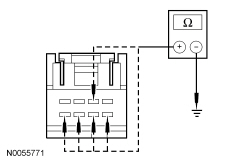
                A2 CHECK FOR GROUND TO EXTERIOR MIRROR CONTROL SWITCH  
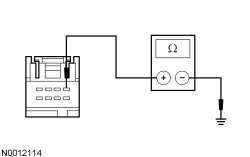
              • Ignition OFF.
              • Measure the resistance between exterior mirror control switch C527-1, circuit GD133 (BK), harness side and ground.


              • Is the resistance less than 5 ohms?
              Yes
              GO to A3 .

              No
              REPAIR the circuit.
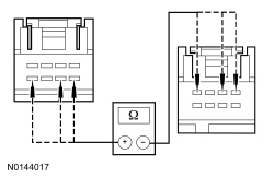
                A3 CHECK COMMON CIRCUIT FOR A SHORT TO VOLTAGE  
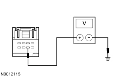
              • Ignition ON.
              • Measure the voltage between exterior mirror control switch C527-6, circuit CPM23 (GY), harness side and ground.


              • Is any voltage present?
              Yes
              REPAIR the circuit.

              No
              GO to A4 .
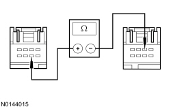
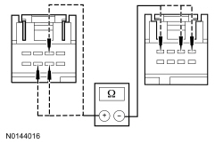
                A4 CHECK COMMON CIRCUIT FOR AN OPEN OR A SHORT TO GROUND  
              • Ignition OFF.
              • Disconnect: LH Exterior Mirror C516.
              • Measure the resistance between exterior mirror control switch C527-6, circuit CPM23 (GY), harness side and ground; and between exterior mirror control switch C527-6, circuit CPM23 (GY), harness side and LH exterior mirror C516-4, circuit CPM23 (GY), harness side.


              • Is the resistance greater than 10,000 ohms between the exterior mirror control switch connector and ground and less than 5 ohms between the exterior mirror control switch connector and the exterior mirror connector?
              Yes
              INSTALL a new exterior mirror control switch. REFER to Exterior Mirror Control Switch .

              No
              REPAIR the circuit.
               

              Pinpoint Test B: A Single Mirror is Inoperative

              Diagnostic Overview

              Diagnostics in this manual assume a certain skill level and knowledge of Ford-specific diagnostic practices. REFER to Diagnostic Methods in Section 100-00 for more information about these practices.

              Refer to Wiring Diagrams Cell 124 , Power Mirrors for schematic and connector information.

              Normal Operation

              The exterior mirror control switch uses circuit CPM23 (GY) as the common circuit for both exterior mirror up/down and right/left movement.

               
              PINPOINT TEST B: A SINGLE MIRROR IS INOPERATIVE
              Test Step Result / Action to Take
                B1 CHECK THE LH EXTERIOR MIRROR  
              • Set the exterior mirror selection switch to the LH mirror position.
              • Use the exterior mirror control switch to operate the LH exterior mirror up,down, left and right.
              • Does the LH exterior mirror operate?
              Yes
              GO to B2 .

              No
              GO to B4 .
                B2 CHECK THE EXTERIOR MIRROR CONTROL SWITCH  
              • Ignition OFF.
              • Disconnect: Exterior Mirror Control Switch C527.
              • Carry out the Exterior Mirror Control Switch Component Test.

                Refer to Wiring Diagrams Cell 149 for component testing.

              • Did the exterior mirror control switch pass the component test?
              Yes
              GO to B3 .

              No
              INSTALL a new exterior mirror control switch. REFER to Exterior Mirror Control Switch .
                B3 CHECK THE RH EXTERIOR MIRROR COMMON CIRCUIT FOR AN OPEN  
              • Disconnect: RH Exterior Mirror C622.
              • Measure the resistance between exterior mirror control switch C527-6, circuit CPM23 (GY), harness side and RH exterior mirror C622-2, circuit CPM23 (GY), harness side.


              • Is the resistance less than 5 ohms?
              Yes
              CHECK the RH exterior mirror jumper harness between the vehicle harness and the exterior mirror motor for open circuits and damaged or pushed-out pins. If the jumper harness is not OK, REPAIR the jumper harness. If the jumper harness cannot be repaired, INSTALL a new exterior mirror. REFER to Exterior Mirror . If the jumper harness is OK, INSTALL a new exterior mirror motor. REFER to Exterior Mirror Motor .

              No
              REPAIR the circuit.
                B4 CHECK THE EXTERIOR MIRROR CONTROL SWITCH  
              • Ignition OFF.
              • Disconnect: Exterior Mirror Control Switch C527.
              • Carry out the Exterior Mirror Control Switch Component Test.

                Refer to Wiring Diagrams Cell 149 for component testing.

              • Did the exterior mirror control switch pass the component test?
              Yes
              GO to B5 .

              No
              INSTALL a new exterior mirror control switch. REFER to Exterior Mirror Control Switch .
                B5 CHECK THE LH EXTERIOR MIRROR COMMON CIRCUIT FOR AN OPEN  
              • Disconnect: LH Exterior Mirror C516.
              • Measure the resistance between exterior mirror control switch C527-6, circuit CPM23 (GY), harness side and LH exterior mirror C516-2, circuit CPM23 (GY), harness side.


              • Is the resistance less than 5 ohms?
              Yes
              CHECK the LH exterior mirror jumper harness between the vehicle harness and the exterior mirror motor for open circuits and damaged or pushed-out pins. If the jumper harness is not OK, REPAIR the jumper harness. If the jumper harness cannot be repaired, INSTALL a new exterior mirror. REFER to Exterior Mirror . If the jumper harness is OK, INSTALL a new exterior mirror motor. REFER to Exterior Mirror Motor .

              No
              REPAIR the circuit.
               

              Pinpoint Test C: A Single Mirror Does Not Operate Correctly

              Diagnostic Overview

              Diagnostics in this manual assume a certain skill level and knowledge of Ford-specific diagnostic practices. REFER to Diagnostic Methods in Section 100-00 for more information about these practices.

              Refer to Wiring Diagrams Cell 124 , Power Mirrors for schematic and connector information.

              Normal Operation

              The exterior mirror control switch controls the LH exterior mirror movement by switching voltage and ground to circuits CPM17 (BU/GN), CPM16 (BN/BU) and CPM23 (GY). The exterior mirror switch controls the RH exterior mirror movement by switching voltage and ground to circuits CPM21 (YE/VT), CPM20 (BN/WH) and CPM23 (GY).

               
              PINPOINT TEST C: A SINGLE MIRROR DOES NOT OPERATE CORRECTLY
              Test Step Result / Action to Take
                C1 CHECK THE EXTERIOR MIRROR CONTROL CIRCUITS FOR A SHORT TO VOLTAGE  
              • Ignition OFF.
              • Disconnect: Exterior Mirror Control Switch C527.
              • Ignition ON.
              • Measure the voltage between ground and exterior mirror control switch:
                • C527-2, circuit CPM21 (YE/VT), harness side.
                • C527-5, circuit CPM17 (BU/GN), harness side.
                • C527-6, circuit CPM23 (GY), harness side.
                • C527-7, circuit CPM20 (BN/WH), harness side.
                • C527-8, circuit CPM16 (BN/BU), harness side.


              • Is any voltage present?
              Yes
              REPAIR the circuit(s).

              No
              GO to C2 .
                C2 CHECK THE EXTERIOR MIRROR CONTROL CIRCUITS FOR A SHORT TO GROUND  
              • Ignition OFF.
              • Measure the resistance between ground and exterior mirror control switch:
                • C527-2, circuit CPM21 (YE/VT), harness side.
                • C527-5, circuit CPM17 (BU/GN), harness side.
                • C527-6, circuit CPM23 (GY), harness side.
                • C527-7, circuit CPM20 (BN/WH), harness side.
                • C527-8, circuit CPM16 (BN/BU), harness side.


              • Are the resistances greater than 10,000 ohms?
              Yes
              GO to C3 .

              No
              REPAIR the circuit(s).
                C3 CHECK THE EXTERIOR MIRROR CONTROL CIRCUITS FOR AN OPEN  
              • NOTE: LH mirror only.
              • Measure the resistance between exterior mirror control switch:
                • C527-6, circuit CPM23 (GY), harness side and LH exterior mirror C516-2, circuit CPM23 (GY), harness side.
                • C527-8, circuit CPM16 (BN/BU), harness side and LH exterior mirror C516-4, circuit CPM16 (BN/BU), harness side.
                • C527-5, circuit CPM17 (BU/GN), harness side and LH exterior mirror C516-1, circuit CPM17 (BU/GN), harness side.


              • NOTE: RH mirror only.
              • Measure the resistance between exterior mirror control switch:
                • C527-6, circuit CPM23 (GY), harness side and RH exterior mirror C622-2, circuit CPM23 (GY), harness side.
                • C527-7, circuit CPM20 (BN/WH), harness side and RH exterior mirror C622-4, circuit CPM20 (BN/WH), harness side.
                • C527-2, circuit CPM21 (YE/VT), harness side and RH exterior mirror C622-1, circuit CPM21 (YE/VT), harness side.


              • Are the resistances less than 5 ohms?
              Yes
              GO to C4 .

              No
              REPAIR the circuit(s).
                C4 CHECK THE EXTERIOR MIRROR CONTROL SWITCH  
              • Ignition OFF.
              • Disconnect: Exterior Mirror Control Switch C527.
              • Carry out the Exterior Mirror Control Switch Component Test.

                Refer to Wiring Diagrams Cell 149 for component testing.

              • Did the exterior mirror control switch pass the component test?
              Yes
              CHECK the LH or RH exterior mirror jumper harness between the vehicle harness and the exterior mirror motor for open or shorted circuits and damaged or pushed-out pins. If the jumper harness is not OK, REPAIR the jumper harness. If the jumper harness cannot be repaired, INSTALL a new LH or RH exterior mirror. REFER to Exterior Mirror . If the jumper harness is OK, INSTALL a new LH or RH exterior mirror motor. REFER to Exterior Mirror Motor .

              No
              INSTALL a new exterior mirror control switch. REFER to Exterior Mirror Control Switch .
               

              Pinpoint Test E: The Heated Exterior Mirror is Inoperative

              Diagnostic Overview

              Diagnostics in this manual assume a certain skill level and knowledge of Ford-specific diagnostic practices. REFER to Diagnostic Methods in Section 100-00 for more information about these practices.

              Refer to Wiring Diagrams Cell 56 , Heated Windows for schematic and connector information.

              Refer to Wiring Diagrams Cell 124 , Power Mirrors for schematic and connector information.

              Normal Operation

              When the rear window defrost switch is pressed on, the HVAC module supplies ground to the rear window defrost relay. When the relay closes, voltage is supplied to BJB fuse 39 (10A), which supplies voltage to the heated exterior mirror glass. The exterior heated mirrors do not share a common ground.

               
              PINPOINT TEST E: THE HEATED EXTERIOR MIRROR IS INOPERATIVE

              NOTICE: Use the correct probe adapter(s) from the Flex Probe Kit when making measurements. Failure to use the correct probe adapter(s) may damage the connector.

              Test Step Result / Action to Take
                E1 CHECK THE OPERATION OF THE HEATED EXTERIOR MIRROR GLASS  
              • Start the engine.
              • Press the rear window defrost switch on.
              • Using an infrared temperature gun, measure the temperature of the exterior mirror glass for approximately 30 seconds, noting changes in temperature.
              • Does the temperature of the exterior glass rise?
              Yes
              The system is operating correctly at this time.

              No
              GO to E2 .
                E2 CHECK THE OPERATION OF THE REAR WINDOW DEFROST SYSTEM  
              • Using an infrared temperature gun, measure the temperature of the rear window for approximately 30 seconds, noting changes in the temperature.
              • Does the temperature of the rear window rise?
              Yes
              GO to E3 .

              No
              REFER to Section 501-11 to diagnose the rear window defrost system.
                E3 CHECK THE VOLTAGE TO THE INOPERATIVE HEATED EXTERIOR MIRROR  
              • Ignition OFF.
              • Disconnect: Inoperative Exterior Mirror C516 (LH) or C622 (RH).
              • Start the engine.
              • With the engine running, press the rear window defrost switch on.
              • Measure the voltage between:


              • Positive Lead Negative Lead
                Pin Circuit Pin Circuit
                LH Mirror
                C516-6 CBB39 (VT/WH) Ground
                RH Mirror
                C622-6 CBB39 (VT/WH) Ground


              • Is the voltage greater than 11 volts?
              Yes
              GO to E4 .

              No
              INSPECT BJB fuse 39 (10A). If OK, REPAIR the circuit. If not OK, REFER to the Wiring Diagrams manual to identify the possible causes of the circuit short.
                E4 CHECK FOR VOLTAGE TO THE HEATED EXTERIOR MIRROR USING THE CONNECTOR GROUND  
              • Measure the voltage between:


              • Positive Lead Negative Lead
                Pin Circuit Pin Circuit
                LH Mirror
                C516-6 CBB39 (VT/WH) C516-8 GD133 (BK)
                RH Mirror
                C622-6 CBB39 (VT/WH) C622-8 GD139 (BK/YE)


              • Is the voltage greater than 11 volts?
              Yes
              GO to E5 .

              No
              REPAIR the circuit.
                E5 CHECK THE EXTERIOR MIRROR JUMPER HARNESS  
              • Ignition OFF.
              • Inspect the exterior mirror jumper harness between the vehicle harness and the mirror motor for:
                • Open or short circuits
                • Damaged or pushed-out pins
                • Corrosion
              • Is the harness OK?
              Yes
              INSTALL a new exterior mirror glass. REFER to Exterior Mirror Glass .

              No
              REPAIR the harness as necessary. If the harness cannot be repaired, INSTALL a new exterior mirror. REFER to Exterior Mirror .