
105-R025D or equivalent

FLU77-4 or equivalent

software with appropriate hardware, or equivalent scan tool
SECTION 501-10: Seating
| 2014 Mustang Workshop Manual
|
DIAGNOSIS AND TESTING
| Procedure revision date: 01/07/2013
|
| Flex Probe Kit
105-R025D or equivalent |
| Fluke 77-IV Digital Multimeter
FLU77-4 or equivalent |
| Vehicle Communication Module (VCM) and Integrated Diagnostic System (IDS)
software with appropriate hardware, or equivalent scan tool |
Principles of Operation
Power Seats
Each power seat uses a 6-way power seat track and 3 electric motors directly controlled by a seat-mounted, 6-way seat control switch for horizontal (forward/rearward), front height and rear height adjustment.
The power lumbar motor pulls and releases a cable in the lumbar assembly to move the backrest in and out.
The power seat motors are hardwired to the seat control and lumbar switches. The circuits are normally at ground through the seat control switch. An individual motor is switched to voltage and ground when a specific adjustment position is selected. Power seats operate independently from the ignition position.
Heated Seats
The heated seat switches and indicators are part of the Front Controls Interface Module (FCIM). The heated seat system operates independently from the other systems controlled by the FCIM and HVAC module.
When a heated seat button is pressed, the FCIM illuminates the heated seat indicator and transmits a system request message to the HVAC module on the module communication network. The HVAC module receives the message and provides ground to the driver or passenger heated seat relay coil circuit to operate the heated seat. The heated seat system can only operate if both modules are communicating correctly on the communication network and the engine is running.
The driver and passenger heated seat relays are located underneath the driver seat cushion frame. With the ignition ON, voltage is supplied from the Smart Junction Box (SJB) to each heated seat relay coil. Battery voltage is also supplied to the heated seat relay contacts (hot at all times). When energized, the heated seat relay coil closes the relay contact to supply battery voltage from the Battery Junction Box (BJB) to the cushion heater mat. The cushion and backrest heater mats are wired in series and each backrest heater mat is directly connected to ground to complete the electrical circuit to heat a seat.
Each cushion heater mat contains a thermostatic switch that closes when cold to complete the heater grid circuit and heat the seat. When hot, the thermostatic switch opens the heater grid circuit and allows the seat to cool. The heated seat indicator illuminates continuously while the thermostatic switch cycles open and closed. The thermostatic switch is serviceable only as part of a new heater mat.
The HVAC module monitors the heated seat relay coil ground circuits for an open, short to ground and short to voltage. If a circuit fault is detected, a DTC is set and the HVAC module disables the affected seat by removing circuit ground to the heated seat relay coil (refer to the HVAC Module DTC Chart in this section). The HVAC module also transmits a network communication message to the FCIM to deactivate the heated seat indicator. PIDs are available in the FCIM using the scan tool to verify heated seat switch operation.
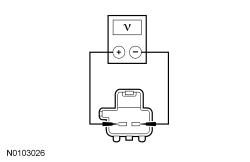
The seat should be occupied to correctly test for normal operation. Temperature measuring devices do not provide an accurate method for testing heated seat operation as surface temperatures are subject to human and environmental characteristics. Correct testing requires heater mat resistance measurements which have tight tolerances affecting heat cycle time length.
The heated seat system does not time-out and will remain on until selected off or engine is off.
Inspection and Verification
Visual Inspection Chart
| Mechanical | Electrical |
|---|---|
|
|
NOTE: Make sure to use the latest scan tool software release.
If the concern is with the heated seat and the cause is not visually evident, connect the scan tool to the Data Link Connector (DLC).NOTE: The Vehicle Communication Module (VCM) LED prove out confirms power and ground from the DLC are provided to the VCM .
If the scan tool does not communicate with the VCM :DTC Chart
HVAC Module DTC Chart
NOTE: This module utilizes a 5-character DTC followed by a 2-character failure type code. The failure type code provides information about specific fault conditions such as opens or shorts to ground. Continuous Memory Diagnostic Trouble Codes (CMDTCs) have an additional 2-character DTC status code suffix to assist in determining DTC history.
| DTC | Description | Action to Take |
|---|---|---|
| B1030: 11 | Left Front Seat Heater Circuit Short To Ground | GO to Pinpoint Test G . |
| B1030: 12 | Left Front Seat Heater Circuit Short To Battery | GO to Pinpoint Test G . |
| B1030: 13 | Left Front Seat Heater Circuit Open | GO to Pinpoint Test G . |
| B1032: 11 | Right Front Seat Heater Circuit Short To Ground | GO to Pinpoint Test H . |
| B1032: 12 | Right Front Seat Heater Circuit Short To Battery | GO to Pinpoint Test H . |
| B1032: 13 | Right Front Seat Heater Circuit Open | GO to Pinpoint Test H . |
| All Other DTCs | — | REFER to the Master DTC Chart in Section 419-10 . |
Symptom Chart
| Condition | Possible Sources | Action |
|---|---|---|
|
| |
|
| |
|
| |
|
| |
|
| |
|
| |
|
| |
|
|
Pinpoint Tests
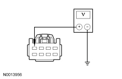
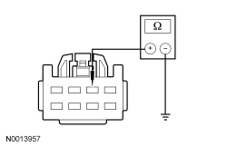
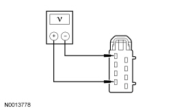
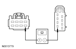
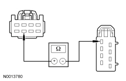
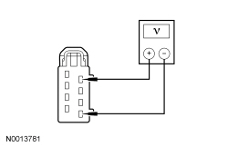
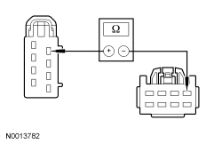
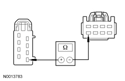
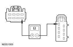
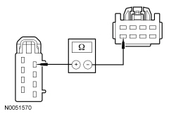
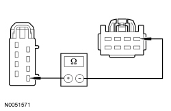
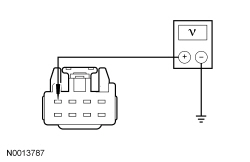
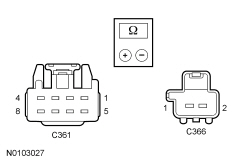
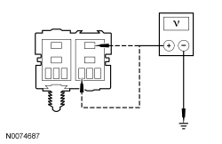
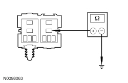
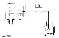
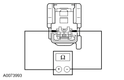
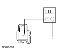
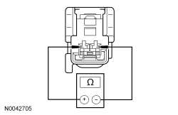
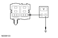
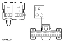
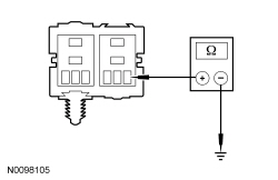
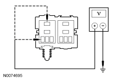
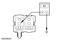
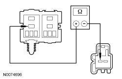
NOTICE: Use the correct probe adapter(s) from the Flex Probe Kit when making measurements. Failure to use the correct probe adapter(s) may damage the connector.
NOTICE: Most faults are due to connector and/or wiring concerns. Carry out a thorough inspection and verification before proceeding with the pinpoint test.
NOTE: The air bag warning indicator illuminates when the correct Restraints Control Module (RCM) fuse is removed and the ignition is ON.
NOTE: The Supplemental Restraint System (SRS) must be fully operational and free of faults before releasing the vehicle to the customer.
Refer to Inspection and Verification and the Symptom Chart for direction to the appropriate pinpoint test.
Pinpoint Test A: The Power Seat is Inoperative — Driver
Refer to Wiring Diagrams Cell 120 , Power Seats for schematic and connector information.
The seat control switch is supplied battery voltage on circuit SBB32 (VT/RD) and ground on circuit GD133 (BK). The seat control switch then supplies voltage and ground to the appropriate circuits to operate the seat motors.
| Test Step | Result / Action to Take |
|---|---|
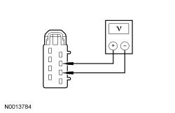
| A1 CHECK FOR VOLTAGE TO THE SEAT CONTROL SWITCH | |
 | Yes
GO to A2 . No VERIFY Battery Junction Box (BJB) fuse 32 (30A) is OK. If OK, REPAIR the circuit. If not OK, REFER to the Wiring Diagrams manual to identify the possible causes of the circuit short. TEST the system for normal operation. DISCONNECT the battery ground cable. CONNECT driver seat side air bag module C367. REPOWER the SRS . REFER to Section 501-20B . |
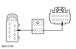
| A2 CHECK THE SEAT CONTROL SWITCH GROUND CIRCUIT FOR AN OPEN | |
 | Yes
INSTALL a new seat control switch. REFER to Seat Control Switch in this section. TEST the system for normal operation. DISCONNECT the battery ground cable. CONNECT driver seat side air bag module C367. REPOWER the SRS . REFER to Section 501-20B . No REPAIR the circuit. TEST the system for normal operation. DISCONNECT the battery ground cable. CONNECT driver seat side air bag module C367. REPOWER the SRS . REFER to Section 501-20B . |
Pinpoint Test B: The Power Seat is Inoperative — Passenger
Refer to Wiring Diagrams Cell 120 , Power Seats for schematic and connector information.
The seat control switch is supplied battery voltage on circuit SBB31 (WH/RD) and ground on circuit GD139 (BK/YE). The seat control switch then supplies voltage and ground to the appropriate circuits to operate the seat motors.
| Test Step | Result / Action to Take |
|---|---|
| B1 CHECK FOR VOLTAGE TO THE SEAT CONTROL SWITCH | |
| Yes
GO to B2 . No VERIFY Battery Junction Box (BJB) fuse 31 (30A) is OK. If OK, REPAIR the circuit. If not OK, REFER to the Wiring Diagrams manual to identify the possible causes of the circuit short. TEST the system for normal operation. DISCONNECT the battery ground cable. CONNECT passenger seat side air bag module C337. REPOWER the SRS . REFER to Section 501-20B . |
| B2 CHECK THE SEAT CONTROL SWITCH GROUND CIRCUIT FOR AN OPEN | |
| Yes
INSTALL a new seat control switch. REFER to Seat Control Switch in this section. TEST the system for normal operation. DISCONNECT the battery ground cable. CONNECT passenger seat side air bag module C337. REPOWER the SRS . REFER to Section 501-20B . No REPAIR the circuit. TEST the system for normal operation. DISCONNECT the battery ground cable. CONNECT passenger seat side air bag module C337. REPOWER the SRS . REFER to Section 501-20B . |
Pinpoint Test C : The Power Seat Does Not Move Horizontally/Vertically — Driver
Refer to Wiring Diagrams Cell 120 , Seating for schematic and connector information.
The seat control switch supplies battery voltage and ground to 1 of 3 power seat track motors through horizontal motor circuits CPS23 (GN/VT) and CPS28 (GN), front height motor circuits CPS24 (GY) and CPS25 (WH/VT) or rear height motor circuits CPS26 (YE/BU) and CPS27 (BU/BN) to move the seat in the desired direction.
| Test Step | Result / Action to Take |
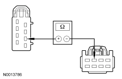
|---|---|
| C1 CHECK THE HORIZONTAL MOTOR FOR CORRECT OPERATION | |
| Yes
If only the front height adjust operates, GO to C2 . If only the rear height adjust operates, GO to C5 . No GO to C8 . |
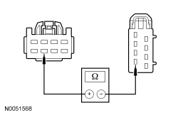
| C2 CHECK THE VOLTAGE TO THE REAR HEIGHT MOTOR | |
 | Yes
INSTALL a new power seat track. REFER to Seat Track — Power in this section. TEST the system for normal operation. DISCONNECT the battery ground cable. CONNECT driver seat side air bag module C367. REPOWER the SRS . REFER to Section 501-20B . No GO to C3 . |
| C3 CHECK THE REAR HEIGHT MOTOR CIRCUIT FOR AN OPEN | |
 | Yes
GO to C4 . No REPAIR the circuit. TEST the system for normal operation. DISCONNECT the battery ground cable. CONNECT driver seat side air bag module C367. REPOWER the SRS . REFER to Section 501-20B . |
| C4 CHECK THE REAR HEIGHT MOTOR CIRCUIT FOR AN OPEN | |
 | Yes
INSTALL a new driver seat control switch. REFER to Seat Control Switch in this section. TEST the system for normal operation. DISCONNECT the battery ground cable. CONNECT driver seat side air bag module C367. REPOWER the SRS . REFER to Section 501-20B . No REPAIR the circuit. TEST the system for normal operation. DISCONNECT the battery ground cable. CONNECT driver seat side air bag module C367. REPOWER the SRS . REFER to Section 501-20B . |
| C5 CHECK FOR VOLTAGE TO THE FRONT HEIGHT MOTOR | |
 | Yes
INSTALL a new power seat track. REFER to Seat Track — Power in this section. TEST the system for normal operation. DISCONNECT the battery ground cable. CONNECT driver seat side air bag module C367. REPOWER the SRS . REFER to Section 501-20B . No GO to C6 . |
| C6 CHECK THE FRONT HEIGHT MOTOR CIRCUIT FOR AN OPEN | |
 | Yes
GO to C7 . No REPAIR the circuit. TEST the system for normal operation. DISCONNECT the battery ground cable. CONNECT driver seat side air bag module C367. REPOWER the SRS . REFER to Section 501-20B . |
| C7 CHECK THE FRONT HEIGHT MOTOR CIRCUIT FOR AN OPEN | |
 | Yes
INSTALL a new driver seat control switch. REFER to Seat Control Switch in this section. TEST the system for normal operation. DISCONNECT the battery ground cable. CONNECT driver seat side air bag module C367. REPOWER the SRS . REFER to Section 501-20B . No REPAIR the circuit. TEST the system for normal operation. DISCONNECT the battery ground cable. CONNECT driver seat side air bag module C367. REPOWER the SRS . REFER to Section 501-20B . |
| C8 CHECK FOR VOLTAGE TO THE HORIZONTAL MOTOR | |
 | Yes
INSTALL a new power seat track. REFER to Seat Track — Power in this section. TEST the system for normal operation. DISCONNECT the battery ground cable. CONNECT driver seat side air bag module C367. REPOWER the SRS . REFER to Section 501-20B . No GO to C9 . |
| C9 CHECK THE HORIZONTAL MOTOR CIRCUIT FOR AN OPEN | |
 | Yes
GO to C10 . No REPAIR the circuit. TEST the system for normal operation. DISCONNECT the battery ground cable. CONNECT driver seat side air bag module C367. REPOWER the SRS . REFER to Section 501-20B . |
| C10 CHECK THE HORIZONTAL MOTOR CIRCUIT FOR AN OPEN | |
 | Yes
INSTALL a new driver seat control switch. REFER to Seat Control Switch in this section. TEST the system for normal operation. DISCONNECT the battery ground cable. CONNECT driver seat side air bag module C367. REPOWER the SRS . REFER to Section 501-20B . No REPAIR the circuit. TEST the system for normal operation. DISCONNECT the battery ground cable. CONNECT driver seat side air bag module C367. REPOWER the SRS . REFER to Section 501-20B . |
Pinpoint Test D: The Power Seat Does Move Horizontally/Vertically — Passenger
Refer to Wiring Diagrams Cell 120 , Seating for schematic and connector information.
The seat control switch supplies battery voltage and ground to 1 of 3 power seat track motors through horizontal motor circuits CPS33 (WH) and CPS38 (GN/BU), front height motor circuits CPS34 (GY/BU) and CPS35 (VT/GN) or rear height motor circuits CPS36 (YE/GY) and CPS37 (WH/BU) to move the seat in the desired direction.
| Test Step | Result / Action to Take |
|---|---|
| D1 CHECK THE HORIZONTAL MOTOR FOR CORRECT OPERATION | |
| Yes
GO to D2 . No GO to D9 . |
| D2 DETERMINE THE SEAT HEIGHT ADJUST FAILURE | |
| Yes
If only the front height adjust operates, GO to D3 . If only the rear height adjust operates, GO to D6 . No INSTALL a new seat control switch. REFER to Seat Control Switch in this section. TEST the system for normal operation. DISCONNECT the battery ground cable. CONNECT passenger seat side air bag module C337. REPOWER the SRS . REFER to Section 501-20B . |
| D3 CHECK FOR VOLTAGE TO THE REAR HEIGHT MOTOR | |
| Yes
INSTALL a new power seat track. REFER to Seat Track — Power in this section. TEST the system for normal operation. DISCONNECT the battery ground cable. CONNECT passenger seat side air bag module C337. REPOWER the SRS . REFER to Section 501-20B . No GO to D4 . |
| D4 CHECK THE REAR HEIGHT MOTOR CIRCUIT FOR AN OPEN | |
 | Yes
GO to D5 . No REPAIR the circuit. TEST the system for normal operation. DISCONNECT the battery ground cable. CONNECT passenger seat side air bag module C337. REPOWER the SRS . REFER to Section 501-20B . |
| D5 CHECK THE REAR HEIGHT MOTOR CIRCUIT FOR AN OPEN | |
 | Yes
INSTALL a new passenger seat control switch. REFER to Seat Control Switch in this section. TEST the system for normal operation. DISCONNECT the battery ground cable. CONNECT passenger seat side air bag module C337. REPOWER the SRS . REFER to Section 501-20B . No REPAIR the circuit. TEST the system for normal operation. DISCONNECT the battery ground cable. CONNECT passenger seat side air bag module C337. REPOWER the SRS . REFER to Section 501-20B . |
| D6 CHECK FOR VOLTAGE TO THE FRONT HEIGHT MOTOR | |
| Yes
INSTALL a new power seat track. REFER to Seat Track — Power in this section. TEST the system for normal operation. DISCONNECT the battery ground cable. CONNECT passenger seat side air bag module C337. REPOWER the SRS . REFER to Section 501-20B . No GO to D7 . |
| D7 CHECK THE FRONT HEIGHT MOTOR CIRCUIT FOR AN OPEN | |
 | Yes
GO to D8 . No REPAIR the circuit. TEST the system for normal operation. DISCONNECT the battery ground cable. CONNECT passenger seat side air bag module C337. REPOWER the SRS . REFER to Section 501-20B . |
| D8 CHECK THE FRONT HEIGHT MOTOR CIRCUIT FOR AN OPEN | |
 | Yes
INSTALL a new passenger seat control switch. REFER to Seat Control Switch in this section. TEST the system for normal operation. DISCONNECT the battery ground cable. CONNECT driver seat side air bag module C337. REPOWER the SRS . REFER to Section 501-20B . No REPAIR the circuit. TEST the system for normal operation. DISCONNECT the battery ground cable. CONNECT passenger seat side air bag module C337. REPOWER the SRS . REFER to Section 501-20B . |
| D9 CHECK FOR VOLTAGE TO THE HORIZONTAL MOTOR | |
| Yes
INSTALL a new power seat track. REFER to Seat Track — Power in this section. TEST the system for normal operation. DISCONNECT the battery ground cable. CONNECT passenger seat side air bag module C337. REPOWER the SRS . REFER to Section 501-20B . No GO to D10 . |
| D10 CHECK THE HORIZONTAL MOTOR CIRCUIT FOR AN OPEN | |
| Yes
GO to D11 . No REPAIR the circuit. TEST the system for normal operation. DISCONNECT the battery ground cable. CONNECT passenger seat side air bag module C337. REPOWER the SRS . REFER to Section 501-20B . |
| D11 CHECK THE HORIZONTAL MOTOR CIRCUIT FOR AN OPEN | |
| Yes
INSTALL a new passenger seat control switch. REFER to Seat Control Switch in this section. TEST the system for normal operation. DISCONNECT the battery ground cable. CONNECT passenger seat side air bag module C337. REPOWER the SRS . REFER to Section 501-20B . No REPAIR the circuit. TEST the system for normal operation. DISCONNECT the battery ground cable. CONNECT passenger seat side air bag module C337. REPOWER the SRS . REFER to Section 501-20B . |
Pinpoint Test E: The Power Lumbar is Inoperative
Refer to Wiring Diagrams Cell 120 , Seating for schematic and connector information.
The lumbar control switch is supplied battery voltage on circuit SBB32 (VT/RD) and ground on circuit GD133 (BK). When the lumbar control switch is pressed, voltage and ground are supplied to the power lumbar motor on circuits CPS65 (WH/GN) and CPS64 (BN/VT) to move the lumbar assembly in or out.
| Test Step | Result / Action to Take | |||||||||
|---|---|---|---|---|---|---|---|---|---|---|
| E1 CHECK THE LUMBAR CONTROL SWITCH FOR VOLTAGE | ||||||||||
 | Yes
GO to E2 . No VERIFY Battery Junction Box (BJB) fuse 32 (30A) is OK. If OK, REPAIR the circuit. If not OK, REFER to the Wiring Diagrams manual to identify the possible causes of the circuit short. TEST the system for normal operation. DISCONNECT the battery ground cable. CONNECT driver seat side air bag module C367. REPOWER the SRS . REFER to Section 501-20B . | |||||||||
| E2 CHECK THE GROUND CIRCUIT FOR AN OPEN | ||||||||||
 | Yes
GO to E3 . No REPAIR the circuit. TEST the system for normal operation. DISCONNECT the battery ground cable. CONNECT driver seat side air bag module C367. REPOWER the SRS . REFER to Section 501-20B . | |||||||||
| E3 CHECK FOR VOLTAGE TO THE LUMBAR MOTOR | ||||||||||
 | Yes
INSTALL a new power lumbar assembly. REFER to Lumbar Assembly in this section. TEST the system for normal operation. DISCONNECT the battery ground cable. CONNECT driver seat side air bag module C367. REPOWER the SRS . REFER to Section 501-20B . No GO to E4 . | |||||||||
| E4 CHECK THE LUMBAR MOTOR CIRCUITS FOR A SHORT TO GROUND | ||||||||||
 | Yes
GO to E5 . No REPAIR the circuit(s). TEST the system for normal operation. DISCONNECT the battery ground cable. CONNECT driver seat side air bag module C367. REPOWER the SRS . REFER to Section 501-20B . | |||||||||
| E5 CHECK THE LUMBAR MOTOR CIRCUITS FOR AN OPEN | ||||||||||
 | Yes
INSTALL a new lumbar control switch. REFER to Lumbar Control Switch in this section. TEST the system for normal operation. DISCONNECT the battery ground cable. CONNECT driver seat side air bag module C367. REPOWER the SRS . REFER to Section 501-20B . No REPAIR the circuit(s). TEST the system for normal operation. DISCONNECT the battery ground cable. CONNECT driver seat side air bag module C367. REPOWER the SRS . REFER to Section 501-20B . |
Pinpoint Test F: The Heated Seats are Inoperative
With the ignition ON, voltage is supplied from the Smart Junction Box (SJB) to each heated seat relay coil on circuit CBP43 (GY). Battery voltage is also supplied to the heated seat relay contacts (hot at all times) on circuit SBB16 (VT/RD). When the heated seat buttons are pressed, the Front Controls Interface Module (FCIM) illuminates the heated seat indicators and transmits a system request message to the HVAC module on the communication network. The HVAC module provides ground to heated seat relay coil circuits CHS30 (GN/YE) (driver) and CHS29 (WH/BU) (passenger) to operate the system. The engine must be running and both modules must be communicating correctly for the system to operate.
The HVAC module monitors the heated seat relay coil circuits for open, short to ground and short to voltage. If circuit faults are detected and DTCs are set for both seats, the HVAC module removes ground from the relay coils to disable the system (refer to HVAC Module DTC Chart in this section). The HVAC module also transmits network communication messages to the FCIM to deactivate the heated seat indicators. PIDs are available in the FCIM using a scan tool to check the heated seat switches and confirm correct module communication.
The heated seat system does not time-out and remains on until switched off or the engine is off.
| Test Step | Result / Action to Take |
|---|---|
| F1 CHECK THE HEATED SEAT INDICATORS | |
| Yes
GO to F4 . No GO to F2 . |
| F2 CHECK SCAN TOOL COMMUNICATION WITH THE FCIM AND MONITOR THE PIDs | |
| Yes
GO to F3 . No If the FCIM does not communicate with the scan tool, REFER to Section 418-00 to diagnose the module communication error. Otherwise, INSTALL a new FCIM . REFER to Section 415-00 . TEST the system for normal operation. |
| F3 RETRIEVE FCIM DTCs | |
| Yes
For all FCIM DTCs, REFER to the Master DTC Chart in Section 419-10 . No GO to F4 . |
| F4 CHECK SCAN TOOL COMMUNICATION WITH THE HVAC MODULE AND RETRIEVE DTCs | |
| Yes
REFER to HVAC Module DTC Chart in this section. No If the HVAC module does not communicate with the scan tool, REFER to Section 418-00 to diagnose the module communication error. Otherwise, GO to F5 . |
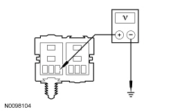
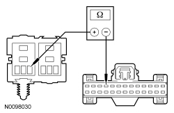
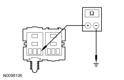
| F5 CHECK FOR VOLTAGE TO THE HEATED SEAT RELAY BOX | |
 | Yes
INSTALL a new HVAC module. REFER to Section 412-01 . REPEAT the self-test. CLEAR the DTCs. TEST the system for normal operation. No VERIFY Battery Junction Box (BJB) fuse 16 (20A) and SJB fuse 43 (10A) are OK. If OK, REPAIR the circuit(s). If not OK, REFER to the Wiring Diagrams manual to identify the possible causes of the circuit short. TEST the system for normal operation. |
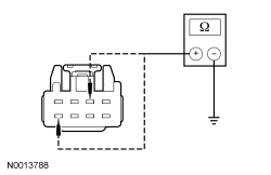
Pinpoint Test G: The Heated Seat is Inoperative/Does Not Operate Correctly — Driver
When the engine is running and the heated seat button is pressed, the Front Controls Interface Module (FCIM) illuminates the heated seat indicator and transmits a system request message to the HVAC module on the module communication network. The HVAC module receives the message and provides ground to the heated seat relay coil circuit CHS29 (WH/BU) to operate the heated seat. Voltage is supplied to the heated seat relay coil circuit CBP43 (GY) and relay contact circuit SBB16 (VT/RD). The relay energizes and supplies voltage to the cushion heater mat on circuit CHS02 (YE/BU). The cushion and backrest heater mats are connected in series by circuit CHS01 (GY/VT) and ground is supplied to the backrest heater mat circuit GD133 (BK), completing the circuit to heat the seat.
The heated seat switch can be checked using a scan tool to monitor the FCIM PID.
The HVAC module reports the following DTCs for the driver heated seat relay coil circuit CHS29 (WH/BU):
| Test Step | Result / Action to Take |
|---|---|
| G1 CHECK THE HEATED SEAT INDICATOR | |
| Yes
GO to G3 . No If the indicator illuminates but does not remain on, GO to G2 . If no indicator illumination and other FCIM functions are inoperative, REFER to Section 415-00 to diagnose the inoperative system(s). Otherwise, INSTALL a new FCIM . REFER to Section 415-00 . |
| G2 RETRIEVE HVAC MODULE DTCs | |
| Yes
If DTC B1030:12, GO to G9 . If DTC B1030:13, GO to G10 . If DTC B1030:11, GO to G11 . For other DTCs, REFER to HVAC Module DTC Chart in this section. No GO to G3 . |
| G3 CHECK FOR VOLTAGE TO THE HEATED SEAT RELAY | |
| Yes
GO to G4 . No VERIFY Battery Junction Box (BJB) fuse 16 (20A) and Smart Junction Box (SJB) fuse 43 (10A) are OK. If OK, REPAIR the circuit(s). If not OK, REFER to the Wiring Diagrams manual to identify the possible causes of the circuit short. TEST the system for normal operation. DISCONNECT the battery ground cable. CONNECT driver seat side air bag C367. REPOWER the SRS . REFER to Section 501-20B . |
| G4 CHECK THE HEATER CIRCUIT FOR AN OPEN | |
 | Yes
INSTALL a new heated seat relay. TEST the system for normal operation. DISCONNECT the battery ground cable. CONNECT driver seat side air bag C367. REPOWER the SRS . REFER to Section 501-20B . No GO to G5 . |
| G5 CHECK THE CUSHION HEATER MAT CIRCUIT FOR AN OPEN | |
 | Yes
GO to G6 . No REPAIR the circuit. TEST the system for normal operation. DISCONNECT the battery ground cable. CONNECT driver seat side air bag C367. REPOWER the SRS . REFER to Section 501-20B . |
| G6 CHECK THE CUSHION HEATER MAT FOR AN OPEN | |
 | Yes
GO to G7 . No INSTALL a new driver cushion heater mat. REFER to Seat Cushion Heater Mat in this section. TEST the system for normal operation. DISCONNECT the battery ground cable. CONNECT driver seat side air bag module C367. REPOWER the SRS . REFER to Section 501-20B . |
| G7 CHECK THE GROUND CIRCUIT FOR AN OPEN | |
 | Yes
GO to G8 . No REPAIR the circuit. TEST the system for normal operation. DISCONNECT the battery ground cable. CONNECT driver seat side air bag module C367. REPOWER the SRS . REFER to Section 501-20B . |
| G8 CHECK THE BACKREST HEATER MAT FOR AN OPEN | |
 | Yes
REPAIR circuit CHS01 (GY/VT). TEST the system for normal operation. DISCONNECT the battery ground cable. CONNECT driver seat side air bag module C367. REPOWER the SRS . REFER to Section 501-20B . No INSTALL a new backrest heater mat. REFER to Seat Backrest Heater Mat in this section. TEST the system for normal operation. DISCONNECT the battery ground cable. CONNECT driver seat side air bag module C367. REPOWER the SRS . REFER to Section 501-20B . |
| G9 CHECK THE HEATED SEAT RELAY COIL CIRCUIT FOR A SHORT TO VOLTAGE | |
 | Yes
REPAIR the circuit. REPEAT the self-test. CLEAR the DTCs. TEST the system for normal operation. No INSTALL a new heated seat relay. REPEAT the self-test. CLEAR the DTCs. TEST the system for normal operation. DISCONNECT the battery ground cable. CONNECT driver seat side air bag module C367. REPOWER the SRS . REFER to Section 501-20B . |
| G10 CHECK THE HEATED SEAT RELAY COIL CIRCUIT FOR AN OPEN | |
 | Yes
INSTALL a new heated seat relay. REPEAT the self-test. CLEAR the DTCs. TEST the system for normal operation. CONNECT driver seat side air bag module C367. REPOWER the SRS . REFER to Section 501-20B . No REPAIR the circuit. REPEAT the self-test. CLEAR the DTCs. TEST the system for normal operation. CONNECT driver seat side air bag module C367. REPOWER the SRS . REFER to Section 501-20B . |
| G11 CHECK THE HEATED SEAT RELAY COIL CIRCUIT FOR A SHORT TO GROUND | |
 | Yes
INSTALL a new heated seat relay. REPEAT the self-test. CLEAR the DTCs. TEST the system for normal operation. CONNECT driver seat side air bag module C367. REPOWER the SRS . REFER to Section 501-20B . No REPAIR the circuit. REPEAT the self-test. CLEAR the DTCs. TEST the system for normal operation. CONNECT driver seat side air bag module C367. REPOWER the SRS . REFER to Section 501-20B . |
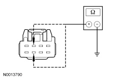
Pinpoint Test H: The Heated Seat is Inoperative/Does Not Operate Correctly — Passenger
When the engine is running and the heated seat button is pressed, the Front Controls Interface Module (FCIM) illuminates the heated seat indicator and transmits a system request message to the HVAC module on the module communication network. The HVAC module receives the message and provides ground to the heated seat relay coil circuit CHS30 (GY/YE) to operate the heated seat. Voltage is supplied to the heated seat relay coil circuit CBP43 (GY) and relay contact circuit SBB16 (VT/RD). The relay energizes and supplies voltage to the cushion heater mat on circuit CHS07 (GY/BU). The cushion and backrest heater mats are connected in series by circuit CHS06 (BU/BN) and ground is supplied to the backrest heater mat circuit GD139 (BK/YE), completing the circuit to heat the seat.
The heated seat switch can be checked using a scan tool to monitor the FCIM PID.
The HVAC module reports the following DTCs for the passenger heated seat relay coil circuit CHS30 (GY/YE):
NOTICE: Do not install a new heater mat on a front passenger seat cushion. Install a new Occupant Classification System (OCS) service kit. Failure to follow this instruction can cause incorrect OCS system operation. Refer to Section 501-20B for the Occupant Classification Sensor Removal and Installation procedure.
| Test Step | Result / Action to Take |
|---|---|
| H1 CHECK THE HEATED SEAT INDICATOR | |
| Yes
GO to H3 . No If the indicator illuminates but does not remain on, GO to H2 . If no indicator illumination and other FCIM functions are inoperative, REFER to Section 415-00 to diagnose the inoperative system(s). Otherwise, INSTALL a new FCIM . REFER to Section 415-00 . |
| H2 RETRIEVE HVAC MODULE DTCs | |
| Yes
If DTC B1032:12, GO to H9 . If DTC B1032:13, GO to H10 . If DTC B1032:11, GO to H11 . For other DTCs, REFER to HVAC Module DTC Chart in this section. No GO to H3 . |
| H3 CHECK FOR VOLTAGE TO THE HEATED SEAT RELAY | |
 | Yes
GO to H4 . No VERIFY Battery Junction Box (BJB) fuse 16 (20A) and Smart Junction Box (SJB) 43 (10A) are OK. If OK, REPAIR the circuit(s). If not OK, REFER to the Wiring Diagrams manual to identify the possible causes of the circuit short. TEST the system for normal operation. DISCONNECT the battery ground cable. CONNECT passenger seat side air bag module C337. REPOWER the SRS . REFER to Section 501-20B . |
| H4 CHECK THE HEATER CIRCUIT FOR AN OPEN | |
 | Yes
INSTALL a new heated seat relay. TEST the system for normal operation. DISCONNECT the battery ground cable. CONNECT passenger seat side air bag module C337. REPOWER the SRS . REFER to Section 501-20B . No GO to H5 . |
| H5 CHECK THE CUSHION HEATER MAT CIRCUIT FOR AN OPEN | |
 | Yes
GO to H6 . No REPAIR the circuit. TEST the system for normal operation. DISCONNECT the battery ground cable. CONNECT passenger seat side air bag C337. REPOWER the SRS . REFER to Section 501-20B . |
| H6 CHECK THE CUSHION HEATER MAT FOR AN OPEN | |
| Yes
GO to H7 . No INSTALL a new passenger cushion heater mat. REFER to Seat Cushion Heater Mat in this section. TEST the system for normal operation. DISCONNECT the battery ground cable. CONNECT passenger seat side air bag module C337. REPOWER the SRS . REFER to Section 501-20B . |
| H7 CHECK THE GROUND CIRCUIT FOR AN OPEN | |
| Yes
GO to H8 . No REPAIR the circuit. TEST the system for normal operation. DISCONNECT the battery ground cable. CONNECT passenger seat side air bag module C337. REPOWER the SRS . REFER to Section 501-20B . |
| H8 CHECK THE BACKREST HEATER MAT FOR AN OPEN | |
| Yes
REPAIR circuit CHS06 (BU/BN). TEST the system for normal operation. DISCONNECT the battery ground cable. CONNECT passenger seat side air bag module C337. REPOWER the SRS . REFER to Section 501-20B . No INSTALL a new backrest heater mat. REFER to Seat Backrest Heater Mat in this section. TEST the system for normal operation. DISCONNECT the battery ground cable. CONNECT passenger seat side air bag module C337. REPOWER the SRS . REFER to Section 501-20B . |
| H9 CHECK THE HEATED SEAT RELAY COIL CIRCUIT FOR A SHORT TO VOLTAGE | |
 | Yes
REPAIR the circuit. REPEAT the self-test. CLEAR the DTCs. TEST the system for normal operation. DISCONNECT the battery ground cable. CONNECT passenger seat side air bag module C337. REPOWER the SRS . REFER to Section 501-20B . No INSTALL a new heated seat relay. REPEAT the self-test. CLEAR the DTCs. TEST the system for normal operation. DISCONNECT the battery ground cable. CONNECT passenger seat side air bag module C337. REPOWER the SRS . REFER to Section 501-20B . |
| H10 CHECK THE HEATED SEAT RELAY COIL CIRCUIT FOR AN OPEN | |
 | Yes
INSTALL a new heated seat relay. REPEAT the self-test. CLEAR the DTCs. TEST the system for normal operation. CONNECT passenger seat side air bag module C337. REPOWER the SRS . REFER to Section 501-20B . No REPAIR the circuit. REPEAT the self-test. CLEAR the DTCs. TEST the system for normal operation. CONNECT passenger seat side air bag module C337. REPOWER the SRS . REFER to Section 501-20B . |
| H11 CHECK THE HEATED SEAT RELAY COIL CIRCUIT FOR A SHORT TO GROUND | |
 | Yes
INSTALL a new heated seat relay. REPEAT the self-test. CLEAR the DTCs. TEST the system for normal operation. CONNECT passenger seat side air bag module C337. REPOWER the SRS . REFER to Section 501-20B . No REPAIR the circuit. REPEAT the self-test. CLEAR the DTCs. TEST the system for normal operation. CONNECT passenger seat side air bag module C337. REPOWER the SRS . REFER to Section 501-20B . |
 WARNING: Make sure no one is in the vehicle and there is nothing blocking or placed in front of any airbag when the battery is connected. Failure to follow these instructions may result in serious personal injury in the event of an accidental deployment.