
105-R025D or equivalent

FLU77-4 or equivalent

SECTION 501-18: Convertible Top
| 2014 Mustang Workshop Manual
|
DIAGNOSIS AND TESTING
| Procedure revision date: 01/07/2013
|
| Flex Probe Kit
105-R025D or equivalent |
| Fluke 77-IV Digital Multimeter
FLU77-4 or equivalent |
|
Vehicle Communication Module (VCM) and Integrated Diagnostic System (IDS) software with appropriate hardware, or equivalent scan tool
|
| Item | Specification |
|---|---|
| MERCON® V Automatic Transmission Fluid
XT-5-QM (or XT-5-QMC) (US); CXT-5-LM12 (Canada) | MERCON® V |
Principles of Operation
The convertible top system is controlled by the Body Control Module B (BCM-B). The convertible top will only function when the accessory delay relay is active and vehicle speed is less than 5 km/h (3 mph). When the convertible top switch is activated, the BCM-B commands the front and rear windows to the full DOWN position. The BCM-B will disable/inhibit the rear quarter window control switch from operating the rear quarter windows when the convertible top ajar switch indicates the convertible top is not in the full UP or full DOWN position. When the BCM-B detects that the LH and RH rear window motors are in the full downward position, it will command the appropriate relay to close in order to raise or lower the convertible top. If the BCM-B does not detect a full down signal from the LH and RH rear window motors, the convertible top operation will be disabled.
The convertible top assembly is a floating frame, Z-fold design. The main pivot brackets are attached to the body, and the convertible top frame side rails expand or fold when the convertible top is raised or lowered. The LH and RH stay pads are attached to the convertible top frame bows, and provide the main source of tension for the convertible top material. When the convertible top is in the full DOWN position, it is stored in the compartment behind the rear seat backrest. When the convertible top is in the full UP position, the body provides a stop which the convertible top frame No. 5 bow contacts to provide a weather seal for the convertible top against the body.
The convertible top hydraulic system uses a reversible hydraulic pump and motor assembly. When activated, the hydraulic pump uses hydraulic pressure to extend the hydraulic lift cylinders to raise the convertible top, or retract the hydraulic lift cylinders to lower the convertible top. The hydraulic motor/pump assembly is equipped with a thermal circuit breaker. In the event of a concern, the circuit breaker will reset after approximately 5 minutes. The thermal circuit breaker is integral to the hydraulic motor and pump assembly and cannot be serviced separately. In the event of a hydraulic system failure, the convertible top cannot be operated manually.
Inspection and Verification
Visual Inspection Chart
| Mechanical | Electrical |
|---|---|
|
|
NOTE: Make sure to use the latest scan tool software release.
If the cause is not visually evident, connect the scan tool to the Data Link Connector (DLC).NOTE: The Vehicle Communication Module (VCM) LED prove out confirms power and ground from the DLC are provided to the VCM .
If the scan tool does not communicate with the VCM :DTC Chart
NOTE: This module utilizes a 5-character DTC followed by a 2-character failure type code. The failure type code provides information about specific fault conditions such as opens or shorts to ground. CMDTCs have an additional 2-character DTC status code suffix to assist in determining DTC history.
Body Control Module B (BCM-B) DTC Chart
| DTC | Description | Action |
|---|---|---|
| B1267:11 | Convertible/Folding Top Activation Up Switch: Circuit Short to Ground | GO to Pinpoint Test A . |
| B1268:11 | Convertible/Folding Top Activation Down Switch: Circuit Short to Ground | GO to Pinpoint Test A . |
| B1269:11 | Convertible/Folding Top Fully Up Position Switch: Circuit Short to Ground | REFER to Section 501-11 . |
| B126D:15 | Convertible/Folding Top Fully Down Position Switch: Circuit Short to Battery or Open | REFER to Section 501-11 . |
| B126E:23 | Right Rear Window Fully Down Feedback: Signal Stuck Low | CLEAR the DTCs. TEST the system for normal operation. REPEAT the self-test. If DTC B126E:23 returns, GO to Pinpoint Test A . |
| B126E:24 | Right Rear Window Fully Down Feedback: Signal Stuck High | CLEAR the DTCs. TEST the system for normal operation. REPEAT the self-test. If DTC B126E:24 returns, GO to Pinpoint Test A . |
| B126F:23 | Left Rear Window Fully Down Feedback: Signal Stuck Low | CLEAR the DTCs. TEST the system for normal operation. REPEAT the self-test. If DTC B126F:23 returns, GO to Pinpoint Test A . |
| B126F:24 | Left Rear Window Fully Down Feedback: Signal Stuck High | CLEAR the DTCs. TEST the system for normal operation. REPEAT the self-test. If DTC B126F:24 returns, GO to Pinpoint Test A . |
| B1278:12 | Convertible/Foldable Top Up Relay: Circuit Short to Battery | GO to Pinpoint Test A . |
| B1278:14 | Convertible/Foldable Top Up Relay: Circuit Short to Ground or Open | GO to Pinpoint Test A . |
| B1279:12 | Convertible/Foldable Top Down Relay: Circuit Short to Battery | GO to Pinpoint Test A . |
| B1279:14 | Convertible/Foldable Top Down Relay: Circuit Short to Ground or Open | GO to Pinpoint Test A . |
| B127A:12 | Global Window Control: Circuit Short to Battery | REFER to Section 501-11 . |
| B127A:14 | Global Window Control: Circuit Short to Ground or Open | REFER to Section 501-11 . |
| All Other DTCs | — | REFER to Section 419-10 . |
Symptom Chart
| Condition | Possible Sources | Action |
|---|---|---|
|
| |
|
| |
|
|
|
|
|
|
Pinpoint Tests
Pinpoint Test A: The Convertible Top Does Not Raise/Lower
Refer to Wiring Diagrams Cell 103 , Convertible Top for schematic and connector information.
Refer to Wiring Diagrams Cell 100 , Power Windows for schematic and connector information.
The convertible top switch supplies a ground signal to the Body Control Module B (BCM-B) on circuit CPR23 (BU/OG) when the convertible top switch is depressed to the lower position, or circuit CPR24 (GN/VT) when the convertible top switch is depressed to the raise position. Ground is supplied to the convertible top switch through circuit GD139 (BK/YE). The convertible top system will not operate when the vehicle speed is greater than 5 km/h (3 mph) or if the ignition switch is in the START position. The convertible top hydraulic system uses a 12-volt reversible pump and motor assembly. When the BCM-B receives a request to operate the convertible top, the BCM-B sends a signal to the front and rear windows to lower the windows to the full DOWN position. The BCM-B monitors the status of the rear windows on circuit CPW53 (YE/OG) for the right rear window, and circuit CPW47 (VT/OG)/CPW53 (YE/OG) for the left rear window. When the BCM-B detects a full down signal from the RH and LH rear window motors, the convertible top operation is enabled. If the BCM-B does not detect a full down signal from the RH and LH rear window motors, the convertible top operation is disabled. When either the convertible top raise relay or the convertible top lower relay is activated, the other relay will remain in its normal state and supplies ground to the hydraulic motor and pump assembly. The convertible top raise and lower relay coils receive voltage at all times from circuit SBB35 (BU/RD). When the convertible top switch is pressed to the lower position, and the BCM-B detects a full down signal from the LH and RH rear window motors, the BCM-B activates the convertible top lower relay by grounding circuit CPR18 (WH/VT). When the convertible top lower relay is activated, voltage is supplied to the hydraulic motor and pump through circuit CPR20 (BU/BN). Ground is supplied to the hydraulic motor and pump assembly through circuit CPR21 (GN). When the convertible top switch is pressed in the raise position, and the BCM-B detects a full down signal from the LH and RH rear window motors, the BCM-B activates the convertible top raise relay by grounding circuit CPR19 (YE/BU). When the convertible top raise relay is activated, voltage is supplied to the hydraulic motor and pump assembly through circuit CPR21 (GN). Ground is supplied to the hydraulic motor and pump assembly through circuit CPR20 (BU/BN).
The hydraulic motor/pump assembly is equipped with a thermal circuit breaker. In the event of a concern, the circuit breaker will reset after approximately 5 minutes. The thermal circuit breaker is integral to the hydraulic motor and pump assembly and cannot be serviced separately.
| DTC Description | Fault Trigger Conditions |
|---|---|
| Short to ground in the convertible top switch raise circuit or switch is active in the raise position during self-test. |
| Short to ground in the convertible top switch lower circuit or switch is active in the lower position during self-test. |
| When the delayed accessory relay is known to be inactive and the RH rear window motor fully down signal is still low, the BCM-B will set this DTC. |
| When the BCM-B does not see the RH rear window fully down signal pulled low, this DTC will set. Convertible top will not operate when this condition is present. |
| When the delayed accessory relay is known to be inactive and the LH rear window motor fully down signal is still low, the BCM-B will set this DTC. |
| When the BCM-B does not see the LH rear window fully down signal pulled low, this DTC will set. Convertible top will not operate when this condition is present. |
| Short to voltage in the convertible top up relay control circuit. |
| Short to ground or open in convertible top up relay control circuit. |
| Short to voltage in the convertible top down relay control circuit. |
| Short to ground or open in convertible top down relay control circuit. |
NOTICE: Use the correct probe adapter(s) when making measurements. Failure to use the correct probe adapter(s) may damage the connector.
| Test Step | Result / Action to Take | |||||||||
|---|---|---|---|---|---|---|---|---|---|---|
| A1 RETRIEVE THE RECORDED DTCs FROM THE BCM-B | ||||||||||
| Yes
For DTC B1267:11 or B1268:11, GO to A6 . For DTC B1278:12, GO to A19 . For DTC B1278:14, VERIFY that Battery Junction Box (BJB) fuse 35 (40A) is OK. If OK, GO to A20 . If not OK, REFER to the Wiring Diagrams manual to identify the possible causes of the circuit short. REPAIR the circuit. CLEAR the DTCs. TEST the system for normal operation. For DTC B1279:12, GO to A21 . For DTC B1279:14, VERIFY that BJB fuse 35 (40A) is OK. If OK, GO to A22 . If not OK, REFER to the Wiring Diagrams manual to identify the possible causes of the circuit short. REPAIR the circuit. CLEAR the DTCs. TEST the system for normal operation. For DTC B126E:23 or B126F:23, GO to A11 . For DTC B126E:24 or B126F:24, GO to A12 . No GO to A2 . | |||||||||
| A2 CHECK THE VEHICLE SPEED INPUT | ||||||||||
| Yes
GO to A3 . No REFER to the Powertrain Control/Emissions Diagnosis (PC/ED) manual to diagnose the VSS . | |||||||||
| A3 CHECK THE CONVERTIBLE/FOLDABLE TOP ACTIVATION SWITCH (CNV_TOP_UP and CNV_TOP_DWN) PID | ||||||||||
| Yes
GO to A9 . No GO to A4 . | |||||||||
| A4 CHECK CIRCUIT 1205 (BK) AT THE CONVERTIBLE TOP SWITCH FOR AN OPEN | ||||||||||
 | Yes
GO to A5 . No REPAIR the circuit. TEST the system for normal operation. | |||||||||
| A5 CHECK CIRCUITS CPR23 (BU/OG) AND CPR24 (GN/VT) FOR AN OPEN | ||||||||||
 | Yes
GO to A6 . No REPAIR the circuit(s). TEST the system for normal operation. | |||||||||
| A6 CHECK CIRCUITS CPR23 (BU/OG) AND CPR24 (GN/VT) FOR A SHORT TO GROUND | ||||||||||
 | Yes
GO to A7 . No REPAIR the circuit(s). CLEAR the DTCs. REPEAT the self-test. | |||||||||
| A7 CHECK THE OPERATION OF THE CONVERTIBLE TOP SWITCH | ||||||||||
| Yes
GO to A8 . No INSTALL a new convertible top switch. REFER to Convertible Top Switch in this section. TEST the system for normal operation. | |||||||||
| A8 CHECK THE CONVERTIBLE TOP SWITCH | ||||||||||
| Yes
GO to A24 . No INSTALL a new convertible top switch. REFER to Convertible Top Switch in this section. CLEAR the DTCs. REPEAT the self-test. | |||||||||
| A9 CHECK THE WINDOW OPERATION | ||||||||||
| Yes
GO to A10 . No REFER to Section 501-11 to diagnose the convertible top drop feature. | |||||||||
| A10 CHECK THE REAR WINDOW FULLY DOWN FEEDBACK (R_WIN_DWN_L and R_WIN_DWN_R) PIDs | ||||||||||
| Yes
GO to A15 . No GO to A12 . | |||||||||
| A11 CHECK THE REAR WINDOW FULLY DOWN SIGNAL CIRCUIT OPERATION | ||||||||||
 | Yes
GO to A24 . No GO to A14 . | |||||||||
| A12 CHECK THE REAR WINDOW FULLY DOWN FEEDBACK (R_WIN_DWN_L or R_WIN_DWN_R) PID | ||||||||||
 | Yes
INSTALL a new LH or RH rear window motor. REFER to Section 501-11 . TEST the system for normal operation. No GO to A13 . | |||||||||
| A13 CHECK CIRCUIT CPW53 (YE/OG) OR CIRCUIT CPW47 (VT/OG) FOR AN OPEN | ||||||||||
 | Yes
GO to A24 . No REPAIR the circuit(s). TEST the system for normal operation. | |||||||||
| A14 CHECK CIRCUIT CPW53 (YE/OG) OR CPW47 (VT/OG) FOR A SHORT TO GROUND | ||||||||||
| Yes
INSTALL a new LH or RH rear window motor as necessary. REFER to Section 501-11 . CLEAR the DTCs. REPEAT the self-test. No REPAIR the circuit(s). CLEAR the DTCs. REPEAT the self-test. | |||||||||
| A15 CHECK FOR CONVERTIBLE TOP MOTOR OPERATION | ||||||||||
 | Yes
GO to A24 . No GO to A16 . | |||||||||
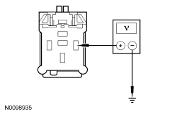
| A16 CHECK FOR VOLTAGE TO THE CONVERTIBLE TOP RELAYS | ||||||||||
 | Yes
GO to A17 . No VERIFY BJB fuse 35 (40A) is OK. If OK, REPAIR the circuit. CLEAR the DTCs. TEST the system for normal operation. If not OK, REFER to the Wiring Diagrams manual to identify the possible cause of the circuit short. REPAIR the circuit. CLEAR the DTCs. TEST the system for normal operation. | |||||||||
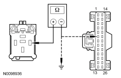
| A17 CHECK CIRCUIT GD110 (BK/WH) FOR AN OPEN | ||||||||||
 | Yes
GO to A18 . No REPAIR the circuit. TEST the system for normal operation. | |||||||||
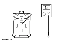
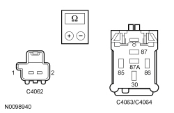
| A18 CHECK THE CONVERTIBLE TOP RELAYS | ||||||||||
| Yes
GO to A19 . If no DTCs, GO to A23 . No INSTALL a new convertible top raise relay or convertible top lower relay. TEST the system for normal operation. | |||||||||
| A19 CHECK CIRCUIT CPR19 (YE/BU) FOR A SHORT TO VOLTAGE | ||||||||||
 | Yes
REPAIR the circuit. CLEAR the DTCs. REPEAT the self-test. No GO to A24 . | |||||||||
| A20 CHECK CIRCUIT CPR19 (YE/BU) FOR A SHORT TO GROUND OR AN OPEN | ||||||||||
 | Yes
CARRY OUT the relay component test for the convertible top raise relay. Refer to Wiring Diagrams Cell 149 for component testing. If the convertible top raise relay does not pass the component test, INSTALL a new convertible top raise relay. CLEAR the DTCs. REPEAT the self-test.If the convertible top raise relay passes the component test, GO to A24 . No REPAIR the circuit. CLEAR the DTCs. REPEAT the self-test. | |||||||||
| A21 CHECK CIRCUIT CPR18 (WH/VT) FOR A SHORT TO VOLTAGE | ||||||||||
| Yes
REPAIR the circuit. CLEAR the DTCs. REPEAT the self-test. No GO to A24 . | |||||||||
| A22 CHECK CIRCUIT CPR18 (WH/VT) FOR A SHORT TO GROUND OR AN OPEN | ||||||||||
 | Yes
CARRY OUT the relay component test for the convertible top lower relay. Refer to Wiring Diagrams Cell 149 for component testing. If the convertible top lower relay does not pass the component test, INSTALL a new convertible top lower relay. CLEAR the DTCs. REPEAT the self-test.If the convertible top lower relay passes the component test, GO to A24 . No REPAIR the circuit. CLEAR the DTCs. REPEAT the self-test. | |||||||||
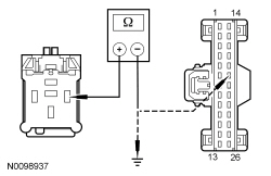
| A23 CHECK CIRCUITS CPR20 (BU/BN) AND CPR21 (GN) FOR AN OPEN | ||||||||||
 | Yes
INSTALL a new convertible top motor. REFER to Hydraulic System, Lift Cylinder and Motor in this section. TEST the system for normal operation. No REPAIR the circuit(s). TEST the system for normal operation. | |||||||||
| A24 CHECK FOR CORRECT BCM-B OPERATION | ||||||||||
| Yes
INSTALL a new BCM-B . REFER to Section 419-10 . CLEAR the DTCs. REPEAT the self-test. No The system is operating correctly at this time. The concern may have been caused by a loose or corroded connector. CLEAR the DTCs. REPEAT the self-test. |
Pinpoint Test B: The Convertible Top Does Not Operate Correctly
Refer to Wiring Diagrams Cell 103 , Convertible Top for schematic and connector information.
The convertible top hydraulic system uses a 12-volt reversible pump and motor assembly. When active, the pump uses hydraulic pressure to extend the hydraulic lift cylinders to raise the convertible top, or retract the hydraulic lift cylinders to lower the convertible top. The convertible top assembly is a floating frame, Z-fold design. The main pivot brackets are attached to the body, and the convertible top frame side rails expand or fold when the convertible top is raised or lowered. The convertible top frame bows attach to the convertible top frame side rails and provide tension for the convertible top material.
| Test Step | Result / Action to Take |
|---|---|
| B1 CHECK THE HYDRAULIC FLUID LEVEL | |
| Yes
GO to B4 . No GO to B2 . |
| B2 CHECK THE HYDRAULIC SYSTEM FOR LEAKS | |
| Yes
REPAIR the leaking hydraulic fitting or INSTALL a new hydraulic hose as necessary. BLEED the hydraulic system. REFER to System Bleeding in this section. TEST the system for normal operation. No GO to B3 . |
| B3 FILL THE HYDRAULIC SYSTEM | |
| Yes
The concern is not present at this time. RETURN the vehicle to the customer. No BLEED the hydraulic system. REFER to System Bleeding in this section. TEST the system for normal operation. |
| B4 CHECK THE CONVERTIBLE TOP LINKAGE | |
| Yes
GO to B5 . No INSTALL new components as necessary. REFER to Convertible Top Bows or Convertible Top Side Rail in this section. TEST the system for normal operation. |
| B5 CHECK THE HYDRAULIC LIFT CYLINDERS | |
| Yes
GO to B6 . No BLEED the hydraulic system. REFER to System Bleeding in this section. If concern is still present after bleeding the hydraulic system, INSTALL a new hydraulic lift cylinder. REFER to Hydraulic System, Lift Cylinder and Motor in this section. TEST the system for normal operation. |
| B6 BLEED THE HYDRAULIC SYSTEM | |
| Yes
The concern is not present at this time. RETURN the vehicle to the customer. No INSTALL a new motor and pump assembly. REFER to Hydraulic System, Lift Cylinder and Motor in this section. TEST the system for normal operation. |