286-00002

286-00001
SECTION 501-35: Body Repairs
| 2014 Mustang Workshop Manual
|
REMOVAL AND INSTALLATION
| Procedure revision date: 01/07/2013
|
| Rust Inhibitor Installation Kit
286-00002 |
| Undercoating Spray Gun
286-00001 |
| 3 Phase Inverter Spot Welder 254-00002 |
| Compuspot 700F Welder 190-50080 |
| I4 Inverter Spot Welder 254-00014 |
| Inverter Welder with MIG Welder 254-00015 |
| Item | Specification |
|---|---|
| Motorcraft® Metal Surface Prep
ZC-31-A | — |
| Premium Undercoating
ValuGard™ VG101, VG101A (aerosol) | — |
| Rust Inhibitor
ValuGard™ VG104, VG104A (aerosol) | — |
 WARNING: Frame rail crush zones absorb crash energy during a collision and must be replaced if damaged. Prior to replacement of frame rail crush zones, straighten damaged frame rails to correct frame dimensions. Failure to follow these instructions may adversely affect frame rail crush zone performance and may result in serious personal injury to vehicle occupants in a crash.
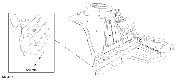
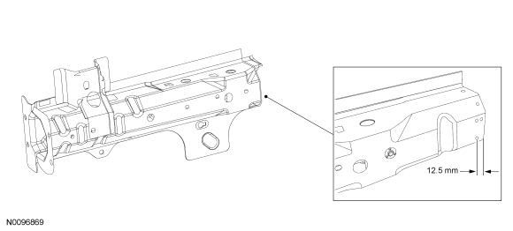
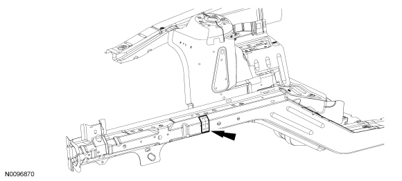
NOTE: Right side shown, left side similar.
NOTE: Cut line shown in illustration is approximate, refer to the following procedure for specific cut locations.
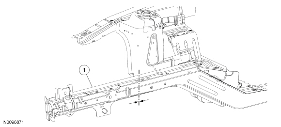
| Item | Part Number | Description |
|---|---|---|
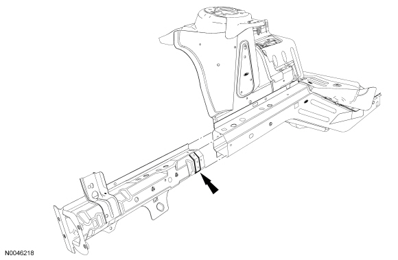
| 1 | 16055 LH/ 16054 RH | Frame rail sectioning kit |
WARNING: Collision damage repair must conform to the instructions contained in this workshop manual. Replacement components must be new, genuine Ford Motor Company parts. Recycled, salvaged, aftermarket or reconditioned parts (including body parts, wheels or safety restraint components) are not authorized by Ford.
Departure from the instructions provided in this manual, including alternate repair methods or the use of substitute components, risks compromising crash safety. Failure to follow these instructions may adversely affect structural integrity and crash safety performance, which could result in serious personal injury to vehicle occupants in a crash.
WARNING: Invisible ultraviolet and infrared rays emitted in welding can injure unprotected eyes and skin. Always use protection such as a welder's helmet with dark-colored filter lenses of the correct density. Electric welding will produce intense radiation, therefore, filter plate lenses of the deepest shade providing adequate visibility are recommended. It is strongly recommended that persons working in the weld area wear flash safety goggles. Also wear protective clothing. Failure to follow these instructions may result in serious personal injury.
WARNING: Always wear protective equipment including eye protection with side shields, and a dust mask when sanding or grinding. Failure to follow these instructions may result in serious personal injury.
NOTICE: This sectioning procedure is only recommended when collision damage does not extend into the front shock tower area. For more severe collision damage, repairs must be made at the original factory seam and joint locations. Failure to follow these instructions may compromise the structural integrity of the vehicle.
NOTE: The following repair procedure illustrates the sectioning of the front side member and fender reinforcement components. In situations where collision damage is less severe, the sectioning procedure to repair only those damaged components may be determined from these procedures.
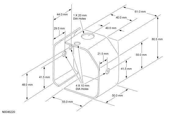
NOTICE: The frame rail sectioning instruction kit provides the specific service procedure instructions for replacement of the frame rail sectioning kit. It is mandatory that the replacement section be installed per the installation guidelines. The frame rail service component must be located to maintain the original factory dimensions. For additional information, refer to Body in this section for correct underbody dimensional information.
Remove the radiator support assembly.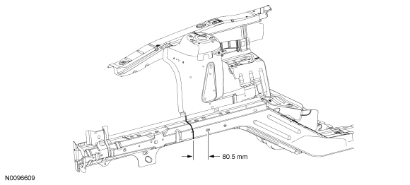
NOTE: Factory spot welds may be substituted with either resistance spot welds or Metal Inert Gas (MIG) plug welds. Spot/plug welds should equal factory welds in both location and quantity. Do not place a new spot weld directly over an original weld location. Plug weld hole should equal 8 mm (0.31 in) diameter.
NOTE: Refer to welding equipment manufacturer's instructions for correct machine set up.
Drill out the spot welds in the front fender apron reinforcement.