
303-1530

303-1248
SECTION 303-01A: Engine — 3.7L
| 2014 Mustang Workshop Manual
|
IN-VEHICLE REPAIR
| Procedure revision date: 01/07/2013
|
 | Hold Down, Secondary Chain
303-1530 |
 | Tool, Camshaft Holding
303-1248 |
| Item | Specification |
|---|---|
| Motorcraft® SAE 5W-20 Premium Synthetic Blend Motor Oil (US); Motorcraft® SAE 5W-20 Super Premium Motor Oil (Canada)
XO-5W20-QSP (US); CXO-5W20-LSP12 (Canada) | WSS-M2C945-A |
Removal
NOTICE: During engine repair procedures, cleanliness is extremely important. Any foreign material, including any material created while cleaning gasket surfaces that enters the oil passages, coolant passages or the oil pan, may cause engine failure.
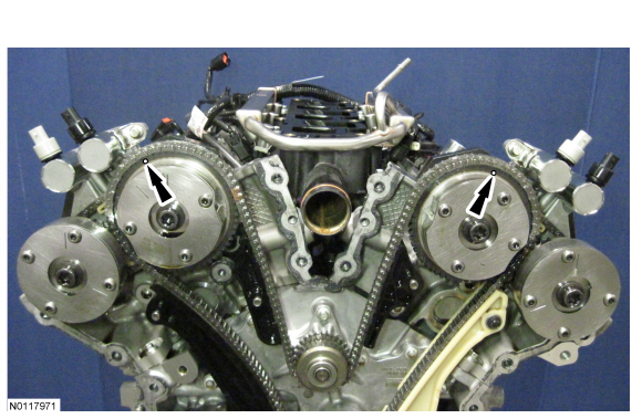
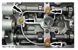
NOTE: The Camshaft Holding Tool will hold the camshafts in the Top Dead Center (TDC) position.
Install the Camshaft Holding Tool onto the flats of the LH camshafts.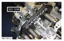
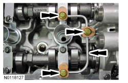
NOTE: The Camshaft Holding Tool will hold the camshafts in the TDC position.
Install the Camshaft Holding Tool onto the flats of the RH camshafts.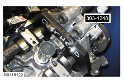
NOTE: The following 3 steps are for primary timing chains that the colored links are not visible.
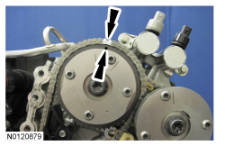
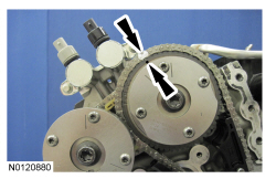
NOTE: The crankshaft sprocket timing mark should be between the 2 colored links.
Mark the 2 timing chain links that align with the timing mark on the crankshaft sprocket as shown.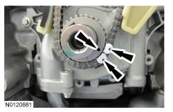
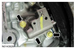
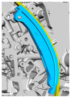
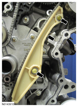
NOTE: Removal of the VCT oil control solenoid will aid in the removal of the primary timing chain.
NOTE: A slight twisting motion will aid in the removal of the VCT oil control solenoid.
NOTE: Keep the VCT oil control solenoid clean of dirt and debris.
Remove the bolt and the LH intake VCT oil control solenoid.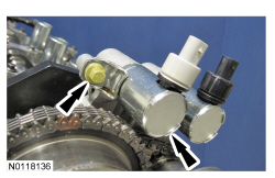
NOTE: Removal of the VCT oil control solenoid will aid in the removal of the primary timing chain.
NOTE: A slight twisting motion will aid in the removal of the VCT oil control solenoid.
NOTE: Keep the VCT oil control solenoid clean of dirt and debris.
Remove the bolt and the RH intake VCT oil control solenoid.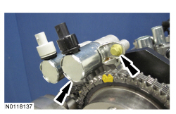
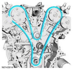
NOTE: The 2 VCT oil control solenoids are removed for clarity.
NOTE: The Secondary Chain Hold Down is inserted through a hole in the top of the mega cap.
Compress the RH secondary timing chain tensioner and install the Secondary Chain Hold Down in the hole on the rear of the secondary timing chain tensioner guide and let it hold against the mega cap to retain the tensioner in the collapsed position.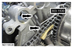
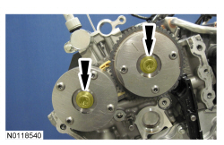
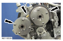
NOTE: When the Camshaft Holding Tool is removed, valve spring pressure may rotate the RH camshafts approximately 3 degrees to a neutral position.
Remove the Camshaft Holding Tool from the RH camshafts.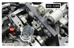
NOTE: Cylinder head camshaft bearing caps are numbered to verify that they are assembled in their original positions.
NOTE: Mark the exhaust and intake camshafts for installation into their original locations.
Remove the 12 bolts, 6 camshaft caps, mega cap and the RH camshafts.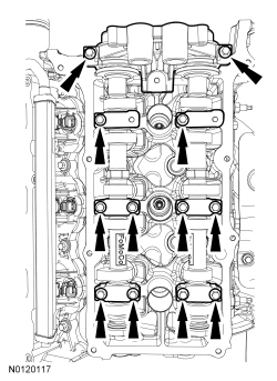
Installation
NOTE: Coat the camshafts with clean engine oil prior to installation.
Position the camshafts onto the RH cylinder head in the neutral position as shown.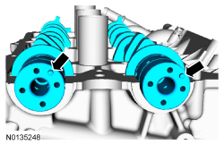
NOTICE: The crankshaft must remain in the freewheeling position (crankshaft dowel pin at 9 o'clock) until after the camshafts are installed and the valve clearance is checked/adjusted. Do not turn the crankshaft until instructed to do so. Failure to follow this process will result in severe engine damage.
Rotate the crankshaft counterclockwise until the crankshaft dowel pin is in the 9 o'clock position.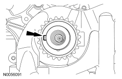
NOTICE: The camshaft seal gaps must be at the 12 o'clock position or damage to the engine may occur.
Position the 4 camshaft seals gaps as shown.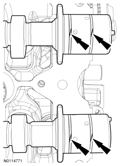
NOTE: Cylinder head camshaft bearing caps are numbered to verify that they are assembled in their original positions.
Install the 6 camshaft caps, mega cap, valve train oil tube and the 15 bolts in the sequence shown.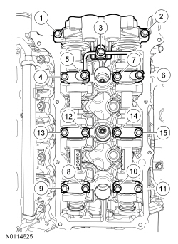
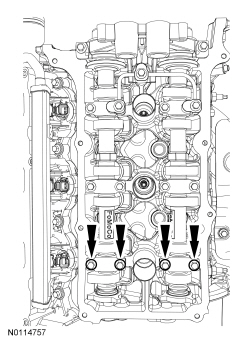
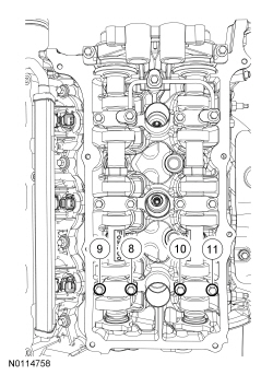
NOTICE: If any components are installed new, the engine valve clearance must be checked/adjusted or engine damage may occur.
NOTE: Use a camshaft sprocket bolt to turn the camshafts.
Using a feeler gauge, confirm that the valve tappet clearances are within specification. If valve tappet clearances are not within specification, the clearance must be adjusted by installing new valve tappet(s) of the correct size. For additional information, refer to Valve Clearance Check in this section.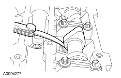

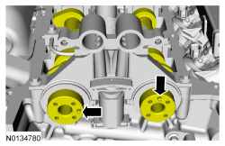
NOTE: The Camshaft Holding Tool will hold the camshafts in the TDC position.
Install the Camshaft Holding Tool onto the flats of the RH camshafts.
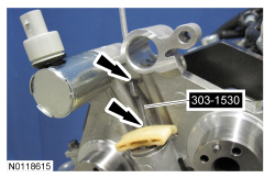
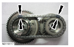
NOTE: It may be necessary to rotate the camshafts slightly, to install the RH secondary timing assembly.
Position the 2 RH VCT assemblies and secondary timing chain onto the camshafts by aligning the holes in the VCT assemblies with the dowel pins in the camshafts.

NOTE: The 2 VCT oil control solenoids are removed for clarity.
Compress the RH secondary timing chain tensioner and remove the Secondary Chain Hold Down.
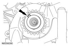
NOTE: It may be necessary to rotate the camshafts slightly, to align the timing marks.
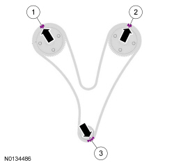
Install the primary timing chain with the colored links aligned with the timing marks on the VCT assemblies and the crankshaft sprocket.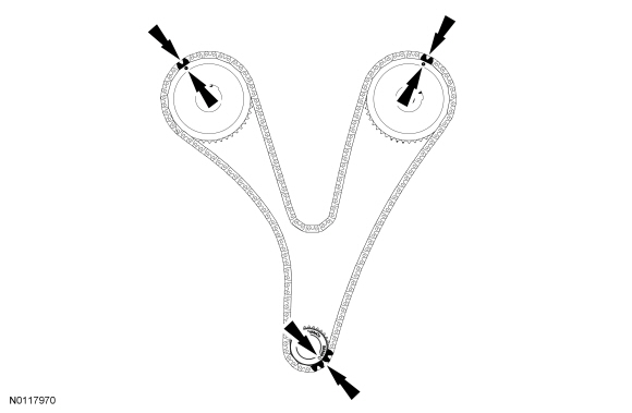


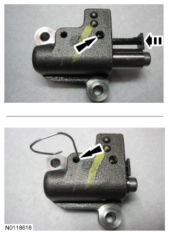
NOTE: It may be necessary to rotate the camshafts slightly to remove slack from the timing chain to install the tensioner.
Install the primary tensioner and the 2 bolts.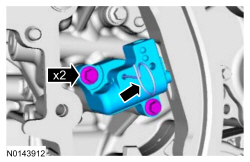
NOTICE: Do not use excessive force when installing the Variable Camshaft Timing (VCT) oil control solenoid. Damage to the mega cap could cause the cylinder head to be inoperable. If difficult to install the VCT oil control solenoid, inspect the bore and VCT oil control solenoid to ensure there are no burrs, sharp edges or contaminants present on the mating surface. Only clean the external surfaces as necessary.
NOTE: A slight twisting motion will aid in the removal of the VCT oil control solenoid.
NOTE: Keep the VCT oil control solenoid clean of dirt and debris.
Install the LH intake VCT oil control solenoid and the bolt.
NOTICE: Do not use excessive force when installing the Variable Camshaft Timing (VCT) oil control solenoid. Damage to the mega cap could cause the cylinder head to be inoperable. If difficult to install the VCT oil control solenoid, inspect the bore and VCT oil control solenoid to ensure there are no burrs, sharp edges or contaminants present on the mating surface. Only clean the external surfaces as necessary.
NOTE: A slight twisting motion will aid in the installation of the VCT oil control solenoid.
NOTE: Keep the VCT oil control solenoid clean of dirt and debris.
Install the RH intake VCT oil control solenoid and the bolt.


