205-153 (T80T-4000-W)

205-149 (T80T-4000-R)

205-150 (T80T-4000-S)
SECTION 303-01A: Engine — 3.7L
| 2014 Mustang Workshop Manual
|
IN-VEHICLE REPAIR
| Procedure revision date: 01/07/2013
|
| Handle
205-153 (T80T-4000-W) |
| Installer, Spindle Bearing
205-149 (T80T-4000-R) |
| Installer, Spindle Bearing
205-150 (T80T-4000-S) |
| Item | Specification |
|---|---|
| Motorcraft® High Performance Engine RTV Silicone
TA-357 | WSE-M4G323-A6 |
| Motorcraft® Metal Surface Prep
ZC-31-A | — |
| Motorcraft® SAE 5W-20 Premium Synthetic Blend Motor Oil (US); Motorcraft® SAE 5W-20 Super Premium Motor Oil (Canada)
XO-5W20-QSP (US); CXO-5W20-LSP12 (Canada) | WSS-M2C945-A |
| Motorcraft® Silicone Gasket Remover
ZC-30 | — |
NOTE: Engine Front Cover (View 1 of 2)
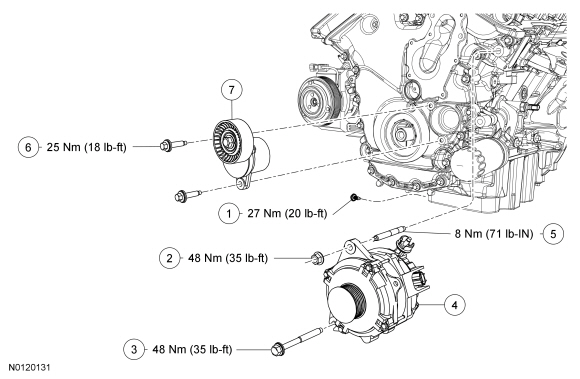
| Item | Part Number | Description |
|---|---|---|
| 1 | 6730 | Oil pan drain plug. |
| 2 | W520414 | Generator nut |
| 3 | W714577 | Generator bolt |
| 4 | 10346 | Generator |
| 5 | W714329 | Generator stud |
| 6 | W713261 | Accessory drive belt tensioner bolt (2 required) |
| 7 | 6B209 | Accessory drive belt tensioner |
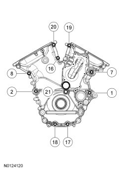
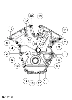
NOTE: Engine Front Cover (View 2 of 2)
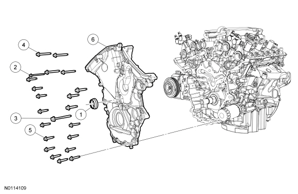
| Item | Part Number | Description |
|---|---|---|
| 1 | 8507 | Front cover radial seal |
| 2 | W503285 | Engine front cover bolt |
| 3 | W714662 | Engine front cover bolt |
| 4 | W503301 | Engine front cover bolt (4 required) |
| 5 | W503297 | Engine front cover bolt (16 required) |
| 6 | 6019 | Engine front cover |
Removal
NOTICE: During engine repair procedures, cleanliness is extremely important. Any foreign material, including any material created while cleaning gasket surfaces that enters the oil passages, coolant passages or the oil pan, may cause engine failure.
NOTE: The front cover radial seal must be replaced.
Using the Spindle Bearing Installer and Handle, remove the front cover radial seal from the rear side of the front cover.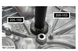
Installation
NOTICE: Only use a 3M™ Roloc® Bristle Disk (2-in white, part number 07528) to clean the engine front cover. Do not use metal scrapers, wire brushes or any other power abrasive disk to clean. These tools cause scratches and gouges that make leak paths.
Clean the engine front cover using a 3M™ Roloc® Bristle Disk (2-in white, part number 07528) in a suitable tool turning at the recommended speed of 15,000 rpm.NOTICE: Place clean, lint-free shop towels over exposed engine cavities. Carefully remove the towels so foreign material is not dropped into the engine. Any foreign material (including any material created while cleaning gasket surfaces) that enters the oil passages or the oil pan may cause engine failure.
NOTICE: Do not use wire brushes, power abrasive discs or 3M™ Roloc® Bristle Disk (2-in white, part number 07528) to clean the sealing surfaces. These tools cause scratches and gouges that make leak paths. They also cause contamination that causes premature engine failure. Remove all traces of the gasket.
Clean the sealing surfaces of the cylinder heads, the cylinder block and the oil pan in the following sequence.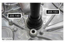
NOTICE: Failure to use Motorcraft® High Performance Engine RTV Silicone may cause the engine oil to foam excessively and result in serious engine damage.
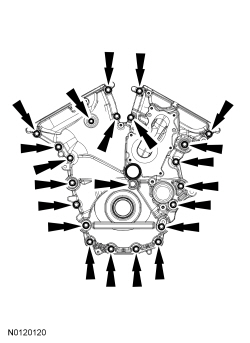
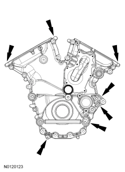
NOTE: The engine front cover and bolts 1, 2, 7, 8, 16, 17, 18, 19, 20 and 21 must be installed within 4 minutes of the initial sealant application. The remainder of the engine front cover bolts and the engine mount bracket bolts must be installed and tightened within 35 minutes of the initial sealant application. If the time limits are exceeded, the sealant must be removed, the sealing area cleaned and sealant reapplied. To clean the sealing area, use silicone gasket remover and metal surface prep. Failure to follow this procedure can cause future oil leakage.
Apply a 3.0 mm (0.11 in) bead of Motorcraft® High Performance Engine RTV Silicone to the engine front cover sealing surfaces including the 2 engine front cover bolt bosses.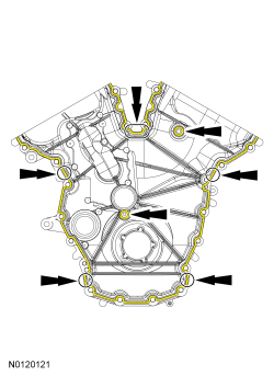
NOTE: Make sure the 2 locating dowel pins are seated correctly in the cylinder block.
Install the engine front cover and bolts 1, 2, 7, 8, 16, 17, 18, 19, 20 and 21.