SECTION 303-01A: Engine — 3.7L
| 2014 Mustang Workshop Manual
|
IN-VEHICLE REPAIR
| Procedure revision date: 04/03/2013
|
| Item | Specification |
|---|---|
| Motorcraft® High Performance Engine RTV Silicone
TA-357 | WSE-M4G323-A6 |
| Motorcraft® Metal Surface Prep
ZC-31-A | — |
| Motorcraft® SAE 5W-20 Premium Synthetic Blend Motor Oil (US); Motorcraft® SAE 5W-20 Super Premium Motor Oil (Canada)
XO-5W20-QSP (US); CXO-5W20-LSP12 (Canada) | WSS-M2C945-A |
| Motorcraft® Silicone Gasket Remover
ZC-30 | — |
Removal
NOTICE: During engine repair procedures, cleanliness is extremely important. Any foreign material, including any material created while cleaning gasket surfaces that enters the oil passages, coolant passages or the oil pan, can cause engine failure.
NOTICE: Place clean, lint-free shop towels over exposed engine cavities. Carefully remove the towels so foreign material is not dropped into the engine. Any foreign material (including any material created while cleaning gasket surfaces) that enters the oil passages or the oil pan, may cause engine failure.
NOTICE: Do not use wire brushes, power abrasive discs or 3M™ Roloc® Bristle Disk (2-in white, part number 07528) to clean the sealing surfaces. These tools cause scratches and gouges that make leak paths. They also cause contamination that will cause premature engine failure. Remove all traces of the gasket.
Clean the sealing surfaces of the cylinder block and oil pan flange in the following sequence.Installation
NOTICE: Failure to use Motorcraft® High Performance Engine RTV Silicone may cause the engine oil to foam excessively and result in serious engine damage.
NOTE: The crankshaft rear seal retainer must be installed and the bolts tightened within 10 minutes of sealant application.
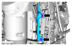
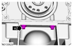
Apply 5 mm (0.196 in) beads of Motorcraft® High Performance Engine RTV Silicone to the 2 cylinder block/oil pan joints.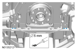
NOTICE: Failure to use Motorcraft® High Performance Engine RTV Silicone may cause the engine oil to foam excessively and result in serious engine damage.
NOTE: The crankshaft rear seal retainer must be installed and the bolts tightened within 10 minutes of sealant application.
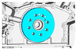
NOTE: The stamped steel crankshaft rear seal retainer plate comes with the crankshaft rear seal.
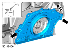
Apply a 3 mm (0.11 in) bead of Motorcraft® High Performance Engine RTV Silicone to the sealing surface of the crankshaft rear seal retainer.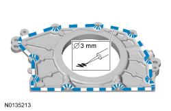
NOTE: Use the 2 handles during installation to avoid touching the sealant.
NOTE: Lubricate the crankshaft rear seal with clean engine oil.
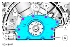
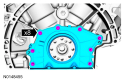
Install the crankshaft rear seal retainer at an angle above the oil pan flange to avoid scraping off the sealer. Tilt the seal retainer up and onto the rear of the cylinder block.