SECTION 303-01A: Engine — 3.7L
| 2014 Mustang Workshop Manual
|
IN-VEHICLE REPAIR
| Procedure revision date: 01/07/2013
|
Lower Intake Manifold
Lower Intake Manifold (View 1 of 3)
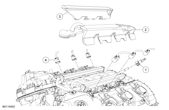
| Item
| Part Number
| Description
| | 1
| —
| Fuel tube-to-fuel rail quick connect coupling (part of 9J280)
|
| 2
| 6P013
| LH fuel rail noise insulator shield
|
| 3
| 6P013
| RH fuel rail noise insulator shield
|
| 4
| —
| Fuel injector electrical connector (part of 12C508) (6 required)
|
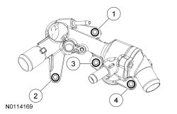
Lower Intake Manifold (View 2 of 3)
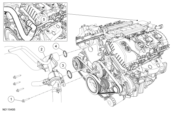
| Item
| Part Number
| Description
| | 1
| W714841
| Thermostat housing bolt (4 required)
|
| 2
| 8592
| Thermostat housing
|
| 3
| 8A571
| Thermostat housing gasket
|
| 4
| 9A425
| Thermostat housing-to-coolant tube O-ring seal
|
| 5
| 18472
| Heater hose-to-lower intake manifold
|
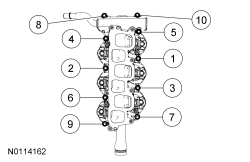
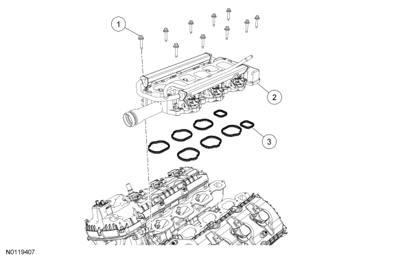
Lower Intake Manifold (View 3 of 3)
| Item
| Part Number
| Description
| | 1
| W503279
| Lower intake manifold bolt (10 required)
|
| 2
| 9424
| Lower intake manifold
|
| 3
| 9439
| Lower intake manifold gasket (8 required)
|
Removal
 WARNING: Do not smoke, carry lighted tobacco or have an open flame of any type when working on or near any fuel-related component. Highly flammable mixtures are always present and may be ignited. Failure to follow these instructions may result in serious personal injury.
WARNING: Before working on or disconnecting any of the fuel tubes or fuel system components, relieve the fuel system pressure to prevent accidental spraying of fuel. Fuel in the fuel system remains under high pressure, even when the engine is not running. Failure to follow this instruction may result in serious personal injury.
WARNING: Do not carry personal electronic devices such as cell phones, pagers or audio equipment of any type when working on or near any fuel-related component. Highly flammable mixtures are always present and may be ignited. Failure to follow these instructions may result in serious personal injury.
WARNING: Always disconnect the battery ground cable at the battery when working on an evaporative emission (EVAP) system or fuel-related component. Highly flammable mixtures are always present and may be ignited. Failure to follow these instructions may result in serious personal injury.
WARNING: Clean all fuel residue from the engine compartment. If not removed, fuel residue may ignite when the engine is returned to operation. Failure to follow this instruction may result in serious personal injury.
NOTICE:
During engine repair procedures, cleanliness is extremely important. Any foreign material, including any material created while cleaning gasket surfaces that enters the oil passages, coolant passages or the oil pan, may cause engine failure.
- Release the fuel system pressure. For additional information, refer to
Section 310-00
.
- Disconnect the battery ground cable. For additional information, refer to
Section 414-01
.
- Drain the cooling system. For additional information, refer to
Section 303-03A
.
- Remove the upper intake manifold. For additional information, refer to
Upper Intake Manifold
in this section.
- Disconnect the fuel tube-to-fuel rail quick connect coupling. For additional information, refer to
Section 310-00
.
- Remove the LH and RH fuel rail noise insulator shields.
- Disconnect the 6 fuel injector electrical connectors.
- Remove the 4 bolts and remove the thermostat housing from the coolant tube.
- Remove and discard the thermostat housing gasket and coolant tube O-ring seal.
- Disconnect the heater hose from the rear of the lower intake manifold. For additional information, refer to
Section 412-00
.
- Remove the 10 bolts and the lower intake manifold.
- Remove and discard the lower intake manifold gaskets.
- Clean and inspect all sealing surfaces.
Installation
NOTICE:
If the engine is repaired or replaced because of upper engine failure, typically including valve or piston damage, check the intake manifold for metal debris. If metal debris if found, install a new intake manifold. Failure to follow these instructions can result in engine damage.
Using new lower intake manifold gaskets, install the lower intake manifold and the 10 bolts and tighten in the sequence shown.
- Tighten to 10 Nm (89 lb-in).
- Connect the heater hose to the lower intake manifold. For additional information, refer to
Section 412-00
.
- Using new thermostat housing gasket and coolant tube O-ring seal, install the thermostat housing and the 4 bolts and tighten in the sequence shown in 2 stages.
- Stage 1: Tighten to 8 Nm (71 lb-in).
- Stage 2: Tighten an additional 45 degrees.
- Connect the 6 fuel injector electrical connectors.
- Install the LH and RH fuel rail noise insulator shields.
- Connect the fuel tube-to-fuel rail quick connect coupling. For additional information, refer to
Section 310-00
.
- Install the upper intake manifold. For additional information, refer to
Upper Intake Manifold
in this section.
- Connect the battery ground cable. For additional information, refer to
Section 414-01
.
- Fill and bleed the cooling system. For additional information, refer to
Section 303-03A
.