
303-1245

303-1529

303-F072

303-1248
SECTION 303-01A: Engine — 3.7L
| 2014 Mustang Workshop Manual
|
IN-VEHICLE REPAIR
| Procedure revision date: 01/07/2013
|
| Eye, Engine Lift
303-1245 |
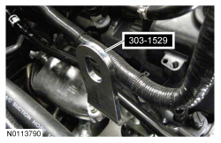
| Lift Eye, RH Front
303-1529 |
| Support Bar, Engine
303-F072 |
| Tool, Camshaft Holding
303-1248 |
Removal
NOTICE: During engine repair procedures, cleanliness is extremely important. Any foreign material, including any material created while cleaning gasket surfaces, that enters the oil passages, coolant passages or the oil pan may cause engine failure.
NOTE: Use a steering wheel holding device (such as Hunter® 28-75-1 or equivalent).
Using a suitable holding device, hold the steering wheel in the straight-ahead position.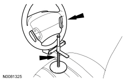
NOTE: RH shown, LH similar.
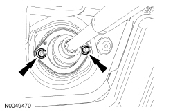
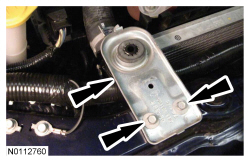
Remove the RH and LH engine mount-to-engine bracket mount nuts.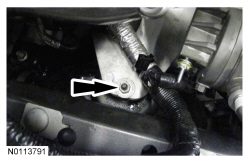
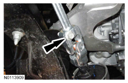
NOTE: RH shown, LH similar.
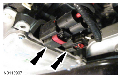
Loosen the 2 nuts for the crossmember brace.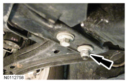
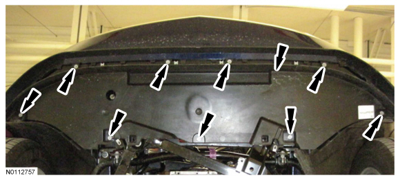
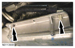
NOTE: RH shown, LH similar.
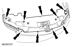
Remove the 6 bolts (2 shown) and slide the crossmember brace forward and remove.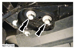
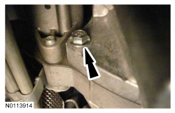
NOTE: RH shown, LH similar.
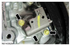
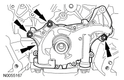
Remove the 4 nuts (2 shown) and the front crossmember brace.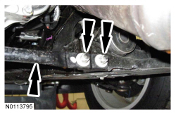
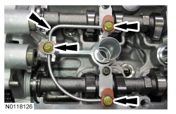
NOTE: The Camshaft Holding Tool will hold the camshafts in the Top Dead Center (TDC) position.
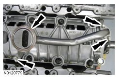
Install the Camshaft Holding Tool onto the flats of the LH camshafts.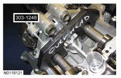
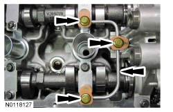
NOTE: The Camshaft Holding Tool will hold the camshafts in the TDC position.
Install the Camshaft Holding Tool onto the flats of the RH camshafts.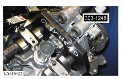
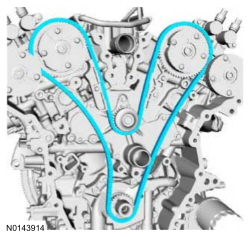
NOTE: The following 3 steps are for primary timing chains that the colored links are not visible.
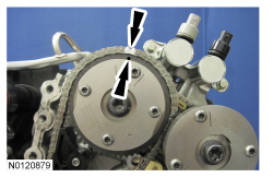
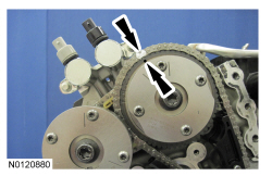
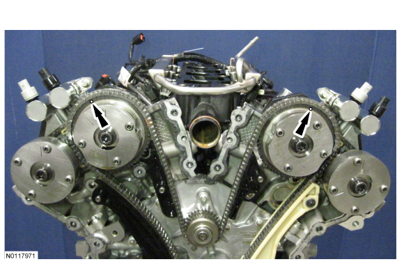
NOTE: The crankshaft sprocket timing mark should be between the 2 colored links.
Mark the 2 timing chain links that align with the timing mark on the crankshaft sprocket as shown.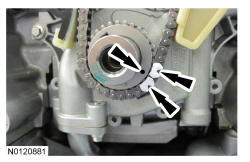
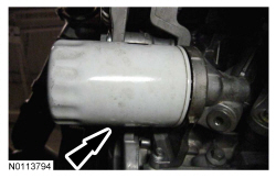
NOTE: Removal of the VCT oil control solenoid will aid in the removal of the primary timing chain.
NOTE: A slight twisting motion will aid in the removal of the VCT oil control solenoid.
NOTE: Keep the VCT oil control solenoid clean of dirt and debris.
Remove the bolt and the LH intake VCT oil control solenoid.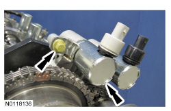
NOTE: Removal of the VCT oil control solenoid will aid in the removal of the primary timing chain.
NOTE: A slight twisting motion will aid in the removal of the VCT oil control solenoid.
NOTE: Keep the VCT oil control solenoid clean of dirt and debris.
Remove the bolt and the RH intake VCT oil control solenoid.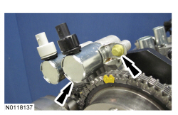
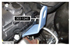
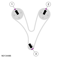
NOTICE: Do not position the legs of the Engine Support Bar on the fenders. Instead, position the legs on the body structure near the suspension strut tower. Failure to follow these instructions may result in body damage.
Install the Engine Support Bar.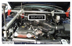
NOTE: Mark the position of the 4 subframe nuts and 4 subframe bolts for reference during installation.
NOTE: RH shown, LH similar.
Remove the 4 rear subframe bolts.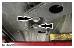
NOTE: RH shown, LH similar.
Remove the 4 front subframe nuts and lower the subframe, using the adjustable jackstand.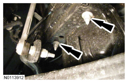
NOTE: The automatic transmission has one more bottom bellhousing-to-oil pan bolt than the manual transmission.
NOTE: Automatic transmission shown, manual transmission similar.
Remove the 2 LH bellhousing-to-oil pan bolts.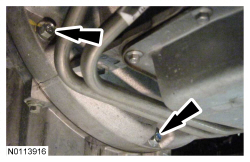
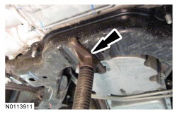
NOTE: LH rear shown, RH front similar.
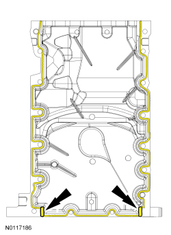
NOTE: The subframe may need to be lowered more for clearance to remove the oil pan.
Using a suitable pry tool, locate the 2 pry pads (1 shown) at the LH and RH side of the oil pan and pry the oil pan loose and remove.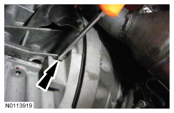
NOTICE: Only use a 3M™ Roloc® Bristle Disk (2-in white, part number 07528) to clean the oil pan. Do not use metal scrapers, wire brushes or any other power abrasive disk to clean. These tools cause scratches and gouges that make leak paths.
Clean the engine oil pan using a 3M™ Roloc® Bristle Disk (2-in white, part number 07528) in a suitable tool turning at the recommended speed of 15,000 rpm.NOTICE: Do not use wire brushes, power abrasive discs or 3M™ Roloc® Bristle Disk (2-in white, part number 07528) to clean the sealing surfaces. These tools cause scratches and gouges that make leak paths. They also cause contamination that causes premature engine failure. Remove all traces of the gasket.
Clean the sealing surfaces of the cylinder block and engine front cover in the following sequence.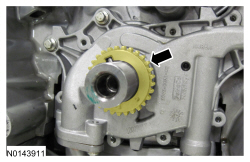
Installation
NOTICE: Failure to use Motorcraft® High Performance Engine RTV Silicone may cause the engine oil to foam excessively and result in serious engine damage.
NOTE: The oil pan and the 4 specified bolts must be installed and the oil pan aligned to the cylinder block within 4 minutes of sealant application. Final tightening of the oil pan bolts must be carried out within 60 minutes of sealant application.
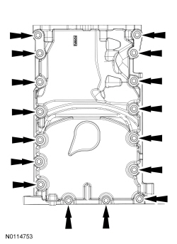
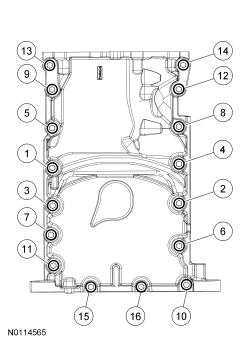
Apply a 3 mm (0.11 in) bead of Motorcraft® High Performance Engine RTV Silicone to the sealing surface of the oil pan-to-engine block mating surface.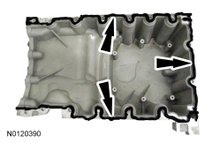
NOTE: The oil pan and the 4 specified bolts must be installed within 4 minutes of the start of sealant application.
Install the oil pan and bolts 10, 11, 13 and 14 finger tight.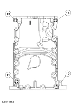
NOTE: The automatic transmission has one more bottom bellhousing-to-oil pan bolt than the manual transmission.
NOTE: Automatic transmission shown, manual transmission similar.
Install and tighten the 2 LH bellhousing-to-oil pan bolts.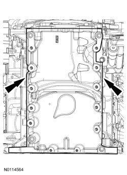
NOTE: The automatic transmission has one more bottom bellhousing-to-oil pan bolt.
Tighten the 2 LH bellhousing-to-oil pan bolts to 48 Nm (35 lb-ft).NOTE: RH shown, LH similar.
Using the adjustable jackstand, raise the subframe and install the 4 front subframe nuts finger tight.NOTE: RH shown, LH similar.
Align the subframe and install the 4 rear subframe bolts with the reference marks made during removal.NOTE: RH shown, LH similar.
Tighten the 4 front subframe nuts to 115 Nm (85 lb-ft).NOTE: It may be necessary to rotate the camshafts slightly, to align the timing marks.
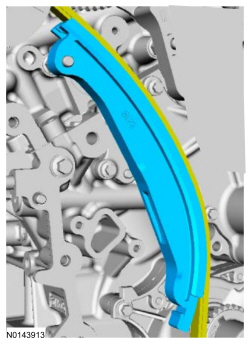
Install the primary timing chain with the colored links aligned with the timing marks on the VCT assemblies and the crankshaft sprocket.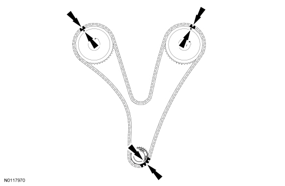
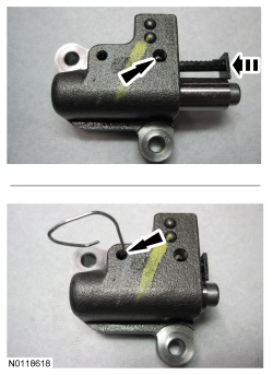
NOTE: It may be necessary to rotate the camshafts slightly to remove slack from the timing chain to install the tensioner.
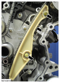
Install the primary timing chain tensioner and the 2 bolts.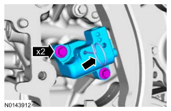
NOTICE: Do not use excessive force when installing the Variable Camshaft Timing (VCT) oil control solenoid. Damage to the mega cap could cause the cylinder head to be inoperable. If difficult to install the VCT oil control solenoid, inspect the bore and VCT oil control solenoid to ensure there are no burrs, sharp edges or contaminants present on the mating surface. Only clean the external surfaces as necessary.
NOTE: A slight twisting motion will aid in the installation of the VCT oil control solenoid.
NOTE: Keep the VCT oil control solenoid clean of dirt and debris.
Install the LH intake VCT oil control solenoid and the bolt.NOTICE: Do not use excessive force when installing the Variable Camshaft Timing (VCT) oil control solenoid. Damage to the mega cap could cause the cylinder head to be inoperable. If difficult to install the VCT oil control solenoid, inspect the bore and VCT oil control solenoid to ensure there are no burrs, sharp edges or contaminants present on the mating surface. Only clean the external surfaces as necessary.
NOTE: A slight twisting motion will aid in the installation of the VCT oil control solenoid.
NOTE: Keep the VCT oil control solenoid clean of dirt and debris.
Install the RH intake VCT oil control solenoid and the bolt.NOTE: Do not lubricate the engine oil filter gasket.
Install a new engine oil filter.NOTE: RH shown, LH similar.
Install the front crossmember brace and the 4 nuts (2 shown).NOTE: RH shown, LH similar.
Install the crossmember brace and the 6 bolts (2 shown).NOTE: RH shown, LH similar.
Tighten the 2 nuts for the crossmember brace to 65 Nm (48 lb-ft).NOTE: RH shown, LH similar.
Install the RH and LH engine mount bracket-to-engine mount nuts.