303-448 (T93P-6303-A)
SECTION 303-01B: Engine — 5.0L (4V)
| 2014 Mustang Workshop Manual
|
IN-VEHICLE REPAIR
| Procedure revision date: 01/07/2013
|
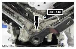
| Holding Tool, Crankshaft
303-448 (T93P-6303-A) |
| Item | Specification |
|---|---|
| Motorcraft® SAE 5W-20 Premium Synthetic Blend Motor Oil (US); Motorcraft® SAE 5W-20 Super Premium Motor Oil (Canada)
XO-5W20-QSP (US); CXO-5W20-LSP12 (Canada) | WSS-M2C945-A |
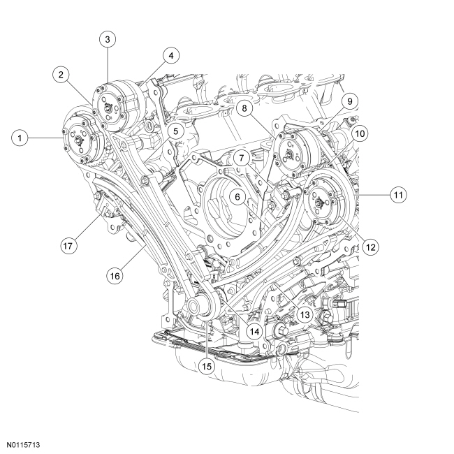
| Item | Part Number | Description |
|---|---|---|
| 1 | 6256 | RH exhaust Variable Camshaft Timing (VCT) assembly |
| 2 | 6K254 | RH secondary timing chain tensioner |
| 3 | 6256 | RH intake VCT assembly |
| 4 | 6268 | RH secondary timing chain |
| 5 | 6M256 | RH timing chain guide |
| 6 | 6K255 | LH timing chain tensioner arm |
| 7 | 6L266 | LH primary timing chain tensioner |
| 8 | 6256 | LH intake VCT assembly |
| 9 | 6268 | LH secondary timing chain |
| 10 | 6K254 | LH secondary timing chain tensioner |
| 11 | 6268 | LH primary timing chain |
| 12 | 6256 | LH exhaust VCT assembly |
| 13 | 6B274 | LH timing chain guide |
| 14 | 6306 | Crankshaft sprocket |
| 15 | 6268 | RH primary timing chain |
| 16 | 6K255 | RH timing chain tensioner arm |
| 17 | 6L266 | RH primary timing chain tensioner |
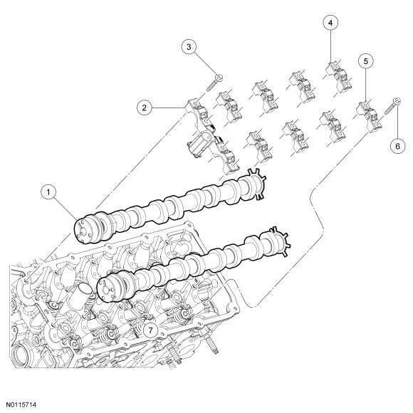
| Item | Part Number | Description |
|---|---|---|
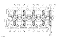
| 1 | 6250 | LH intake camshaft |
| 2 | — | Front camshaft bearing mega cap (part of 6049) |
| 3 | N806183 | Front camshaft bearing mega cap bolt (4 required) |
| 4 | — | Intake camshaft bearing cap (part of 6049) (4 required) |
| 5 | — | Exhaust camshaft bearing cap (part of 6049) (4 required) |
| 6 | N806183 | Intake/exhaust camshaft bearing cap bolt (16 required) |
| 7 | 6250 | LH exhaust camshaft |
Removal
NOTICE: During engine repair procedures, cleanliness is extremely important. Any foreign material, including any material created while cleaning gasket surfaces, that enters the oil passages, coolant passages or the oil pan, can cause engine failure.
NOTE: If the RH camshafts are being serviced at the same time as the LH camshafts, remove the RH camshafts first. For additional information, refer to Camshaft — RH in this section.
NOTE: If the components are to be reinstalled, they must be installed in their original location. Mark the components for installation into their original location.
NOTE: It may be necessary to rotate the crankshaft slightly to provide enough slack in the chain to remove the RH timing chain tensioner arm. Return the crankshaft keyway to the 12 o'clock position after removing the RH timing chain tensioner arm.
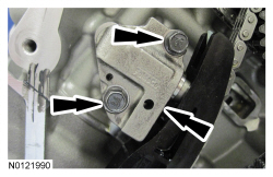
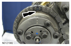
Remove the RH timing chain tensioner arm.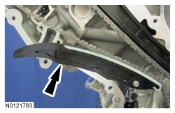
NOTE: It may be necessary to rotate the crankshaft slightly to provide enough slack in the chain to remove the RH timing chain guide. Return the crankshaft keyway to the 12 o'clock position after removing the RH timing chain guide.
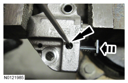
Remove the bolt and the RH timing chain guide.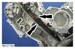
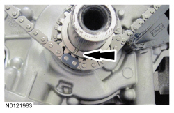
NOTE: It may be necessary to rotate the crankshaft slightly to provide enough slack in the chain to remove the LH timing chain tensioner arm. Return the crankshaft keyway to the 9 o'clock position after removing the LH timing chain tensioner arm.
Remove the LH timing chain tensioner arm.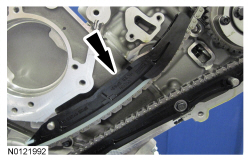
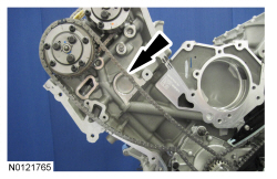
NOTE: It may be necessary to rotate the crankshaft slightly to provide enough slack in the chain to remove the LH timing chain guide. Return the crankshaft keyway to the 9 o'clock position after removing the LH timing chain guide.
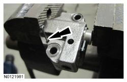
Remove the bolt and the LH timing chain guide.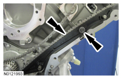

NOTE: Intake camshaft shown, exhaust camshaft similar.
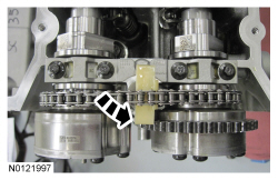
Remove the VCT system oil filter from the intake and exhaust camshafts.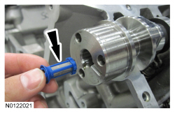
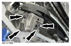
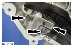
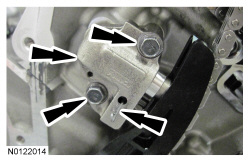
NOTICE: The front camshaft bearing mega cap must be removed first and then the remaining camshaft bearing caps. Failure to follow this direction may result in damage to the engine.
Remove the 4 bolts and the LH front camshaft bearing mega cap.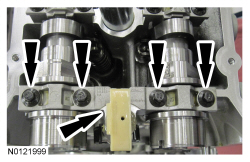
Installation
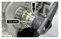
NOTE: Lubricate the camshafts with clean engine oil prior to installation.
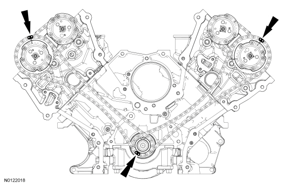
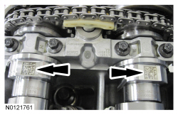
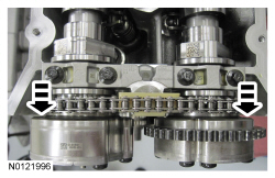
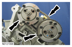
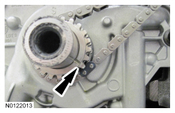
Install the LH intake and exhaust camshafts in the neutral position. Align the D-slots as shown in the illustration.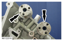
NOTE: Intake camshaft shown, exhaust camshaft similar.
Install the VCT system oil filter in the intake and exhaust camshafts.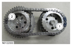
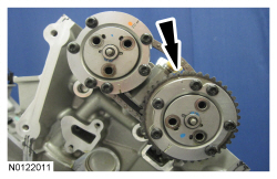
NOTE: It may be necessary to rotate the exhaust camshaft slightly (using a wrench on the flats of the camshaft) to seat the VCT assemblies onto the camshafts.
Rotate the secondary timing chain tensioner 90 degrees so the ramped area is facing forward and fully seat the VCT assemblies onto the camshafts.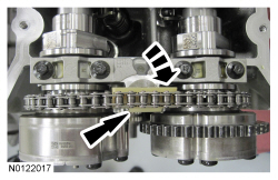
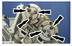
NOTE: Use a wrench on the flats of the camshaft to hold the camshafts while tightening the VCT assembly bolts.
Install the 3 LH intake VCT assembly bolts and the 3 LH exhaust VCT assembly bolts.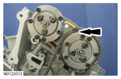
NOTE: It may be necessary to rotate the crankshaft slightly to provide enough slack in the chain to install the LH timing chain guide. Return the crankshaft keyway to the 9 o'clock position after installing the LH timing chain guide.
Install the LH timing chain guide and bolt.NOTE: It may be necessary to rotate the crankshaft slightly to provide enough slack in the chain to install the LH timing chain tensioner arm. Return the crankshaft keyway to the 9 o'clock position after installing the LH timing chain tensioner arm.
Install the LH timing chain tensioner arm.NOTE: Complete the following 3 steps on both the LH and RH primary timing chain tensioners.
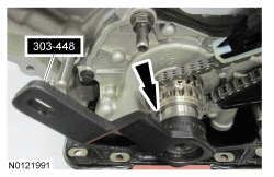
NOTICE: Do not compress the ratchet assembly or damage to the tensioner will occur.
Compress the primary timing chain tensioner plunger, using an edge of a vise.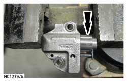
NOTE: It may be necessary to rotate the crankshaft slightly to provide enough slack in the chain to install the RH timing chain guide. Return the crankshaft keyway to the 12 o'clock position after installing the RH timing chain guide.
Install the RH timing chain guide and bolt.NOTE: It may be necessary to rotate the crankshaft slightly to provide enough slack in the chain to install the RH timing chain tensioner arm. Return the crankshaft keyway to the 12 o'clock position after installing the RH timing chain tensioner arm.
Install the RH timing chain tensioner arm.