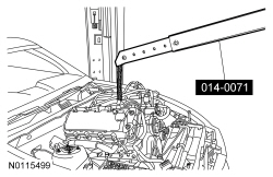
014-00071 or equivalent

303-F047 (014-00073) or equivalent

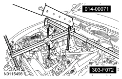
303-F072
SECTION 303-01B: Engine — 5.0L (4V)
| 2014 Mustang Workshop Manual
|
REMOVAL
| Procedure revision date: 01/07/2013
|
| Heavy Duty Floor Crane
014-00071 or equivalent |
| Lifting Bracket, Engine
303-F047 (014-00073) or equivalent |
| Support Bar, Engine
303-F072 |
 WARNING: Do not smoke, carry lighted tobacco or have an open flame of any type when working on or near any fuel-related component. Highly flammable mixtures are always present and may be ignited. Failure to follow these instructions may result in serious personal injury.
WARNING: Before working on or disconnecting any of the fuel tubes or fuel system components, relieve the fuel system pressure to prevent accidental spraying of fuel. Fuel in the fuel system remains under high pressure, even when the engine is not running. Failure to follow this instruction may result in serious personal injury.
WARNING: Do not breathe dust or use compressed air to blow dust from storage containers or friction components. Remove dust using government-approved techniques. Friction component dust may be a cancer and lung disease hazard. Exposure to potentially hazardous components may occur if dusts are created during repair of friction components, such as brake pads and clutch discs. Exposure may also cause irritation to skin, eyes and respiratory tract, and may cause allergic reactions and/or may lead to other chronic health effects. If irritation persists, seek medical attention or advice. Failure to follow these instructions may result in serious personal injury.
NOTE: Use a steering wheel holding device (such as Hunter® 28-75-1 or equivalent).
Using a suitable holding device, hold the steering wheel in the straight-ahead position.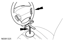
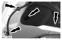
NOTE: Index-mark the hood hinge location to aid in hood installation.
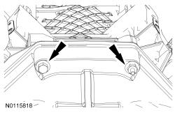
NOTE: RH shown, LH similar.
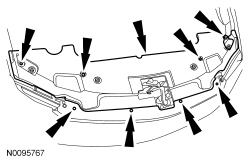
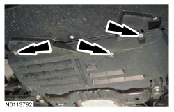
Remove the 4 bolts (2 shown) and the hood.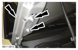
NOTE: The engine appearance cover rubber grommets may remain on the cover. If so, remove the grommets from the cover and install them on the intake manifold before installing the cover.
If equipped, remove the engine appearance cover.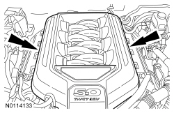
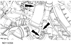
NOTE: It is not necessary to separate the Air Cleaner (ACL) outlet pipe and the ACL , the 2 components can be removed as an assembly.
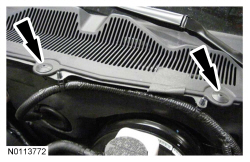
Remove the ACL outlet pipe and the ACL . For additional information, refer to the exploded view in Section 303-12 .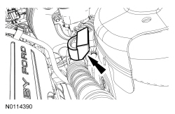
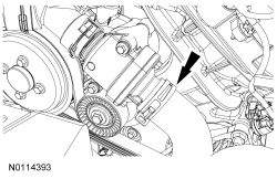
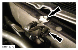
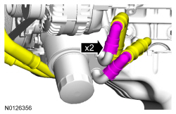
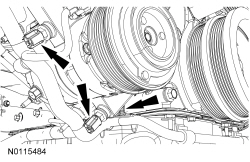
NOTE: Protective rubber cover removed from graphic for clarity.
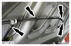
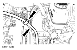
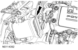
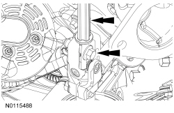
Position aside the protective rubber cover and remove the nut, the B+ cable and the electrical connector from the generator.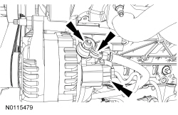
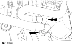
NOTICE: Support the H-pipe with a length of mechanics wire. Do not bend, twist or allow the exhaust side pipes to hang from the flexible bellows or damage to the exhaust side pipe may occur.
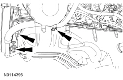
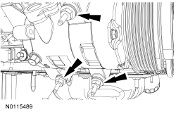
Remove the RH and LH catalytic converters. For additional information, refer to Section 309-00 .NOTE: RH shown, LH similar.
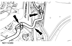
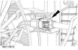
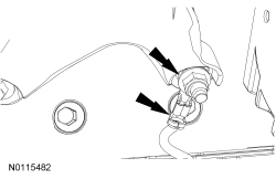
Disconnect the RH and LH Heated Oxygen Sensor (HO2S) electrical connectors.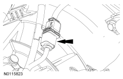
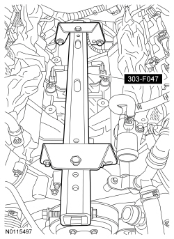
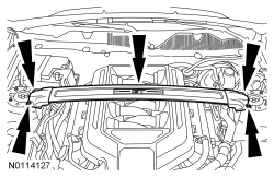
NOTICE: Do not position the legs of the Engine Support Bar on the fenders. Instead, the legs should be positioned on the body structure near the suspension strut tower. Failure to follow these instructions may result in body damage.
Install the Engine Support Bar.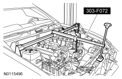
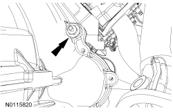
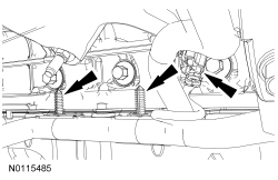
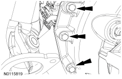
NOTE: RH shown, LH similar.
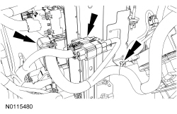
Remove the RH and LH engine support insulator nuts.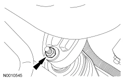
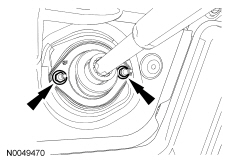
NOTE: The RH engine support insulator has been removed from the graphic for clarity.
Remove the 2 bolts, the 2 stud bolts and the RH engine support insulator bracket.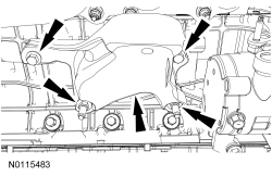
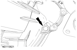
NOTE: The LH engine support insulator has been removed from the graphic for clarity.
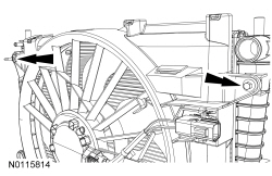
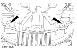
Remove the 3 bolts, the stud bolt and the LH engine support insulator bracket.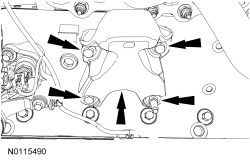
NOTICE: Do not support the transmission by the fluid pan, failure to follow this instruction may result in serious damage to the transmission.
Support the bellhousing of the transmission with a suitable floor jack and a block of wood.