303-D121 or equivalent

205-153 (T80T-4000-W)

303-448 (T93P-6303-A)

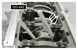
303-442 (T93P-6136-A)

205-142 (T80T-4000-J)

303-519 (T95P-6701-EH)

303-409 (T92C-6700-CH)

303-1247/1

100-001 (T50T-100-A)
SECTION 303-01B: Engine — 5.0L (4V)
| 2014 Mustang Workshop Manual
|
DISASSEMBLY
| Procedure revision date: 01/07/2013
|
| 3 Jaw Puller
303-D121 or equivalent |
| Handle
205-153 (T80T-4000-W) |
| Holding Tool, Crankshaft
303-448 (T93P-6303-A) |
| Installer, Connecting Rod
303-442 (T93P-6136-A) |
| Installer, Differential Bearing Cone
205-142 (T80T-4000-J) |
| Remover, Crankshaft Rear Oil Seal
303-519 (T95P-6701-EH) |
| Remover, Oil Seal
303-409 (T92C-6700-CH) |
| Remover, Spark Plug Tube Seal
303-1247/1 |
| Slide Hammer
100-001 (T50T-100-A) |
| Item | Specification |
|---|---|
| Motorcraft® Metal Surface Prep
ZC-31-A | — |
| Motorcraft® Silicone Gasket Remover
ZC-30 | — |
NOTICE: During engine repair procedures, cleanliness is extremely important. Any foreign material, including any material created while cleaning gasket surfaces, that enters the oil passages, coolant passages or the oil pan, can cause engine failure.
NOTICE: Remove the cylinder heads before removing the crankshaft. Failure to do so can result in engine damage.
NOTE: If the components are to be reinstalled, they must be installed in their original location. Mark the components for installation into their original location.
NOTE: For additional information, refer to the exploded view under the Assembly procedure in this section.
NOTICE: Loosen the bolts evenly to prevent clutch pressure plate damage.
NOTE: If the parts are to be reused, index-mark the pressure plate to the flywheel.
If equipped, remove the 9 pressure plate bolts, remove the pressure plate and the clutch disc.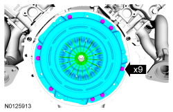
NOTE: Flexplate shown, flywheel similar.
NOTE: The flexplate/flywheel bolts are torque-to-yield design and are not reusable.
Remove the 8 bolts and the flywheel or flexplate.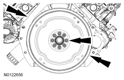
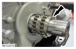
NOTE: Inspect the crankshaft sensor ring for damage. If the crankshaft sensor ring has been dropped or has any visual damage, it must be discarded.
Remove the crankshaft sensor ring.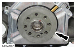
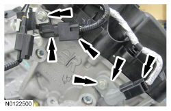

NOTE: RH shown, LH similar.
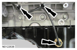
Disconnect the 4 Variable Camshaft Timing (VCT) variable force solenoid electrical connectors.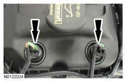
NOTE: RH shown, LH similar.
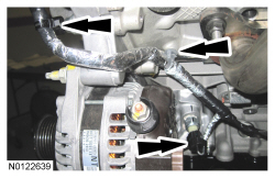
Disconnect the 8 ignition coil electrical connectors.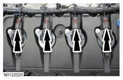
NOTE: RH shown, LH similar.
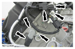
Detach the 9 wiring harness retainers from the RH valve cover and the 10 wiring harness retainers from the LH valve cover.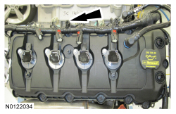

NOTE: When removing the ignition coils, a slight twisting motion will break the seal and ease removal. RH shown, LH similar.
Remove the 8 bolts and the 8 ignition coils.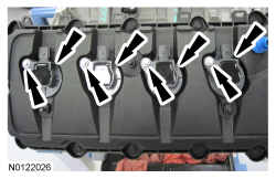
NOTICE: Do not use metal scrapers, wire brushes, power abrasive discs or other abrasive means to clean the sealing surfaces. These tools cause scratches and gouges which make leak paths. Use a plastic scraping tool to remove all traces of old sealant.
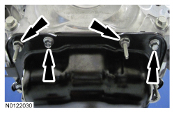
Loosen the 14 bolts and remove the RH valve cover and gasket.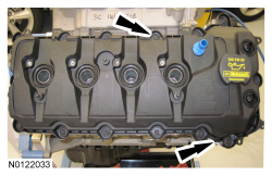
NOTICE: Do not use metal scrapers, wire brushes, power abrasive discs or other abrasive means to clean the sealing surfaces. These tools cause scratches and gouges which make leak paths. Use a plastic scraping tool to remove all traces of old sealant.
Loosen the 14 bolts and remove the LH valve cover and gasket.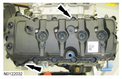
NOTE: RH shown, LH similar.
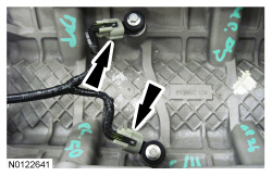
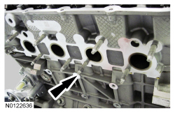
Inspect the 2 VCT variable force solenoid seals. Remove any damaged seals.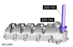
NOTE: RH shown, LH similar.
Inspect the spark plug tube seals. Remove any damaged seals.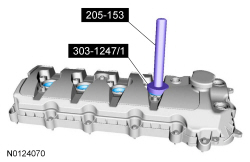
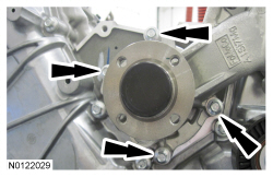
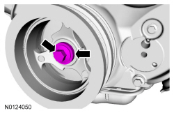
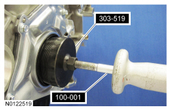
NOTICE: Use care not to damage the engine front cover or the crankshaft when removing the seal.
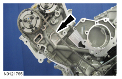
Using the Oil Seal Remover, remove the crankshaft front oil seal.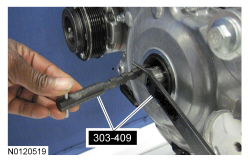
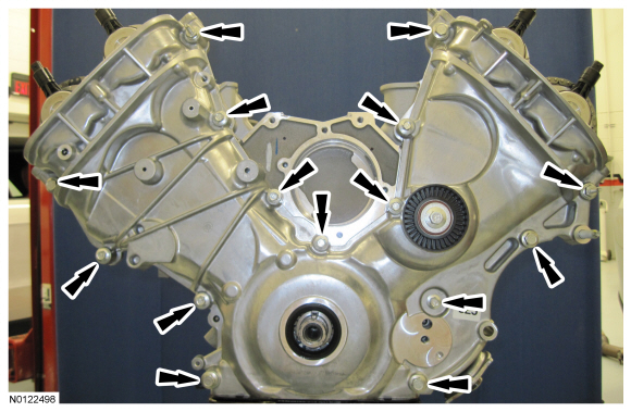
NOTICE: Do not use metal scrapers, wire brushes, power abrasive discs or other abrasive means to clean the sealing surfaces. These tools cause scratches and gouges which make leak paths. Use a plastic scraping tool to remove all traces of old sealant.
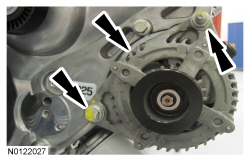
Remove the engine front cover from the front cover to cylinder block dowel.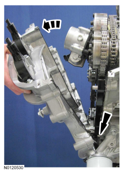
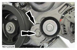
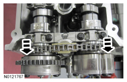
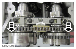
NOTE: It may be necessary to rotate the crankshaft slightly to provide enough slack in the chain to remove the RH timing chain tensioner arm. Return the crankshaft keyway to the 12 o'clock position after removing the RH timing chain tensioner arm.
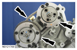
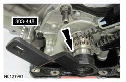
Remove the RH timing chain tensioner arm.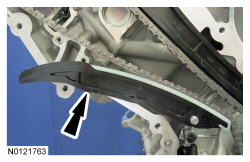
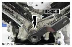
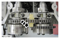
NOTE: It may be necessary to rotate the crankshaft slightly to provide enough slack in the chain to remove the RH timing chain guide. Return the crankshaft keyway to the 12 o'clock position after removing the RH timing chain guide.
Remove the bolt and the RH timing chain guide.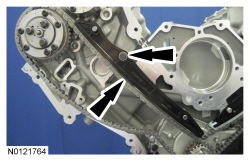
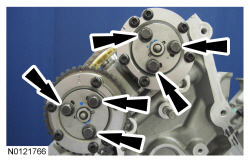
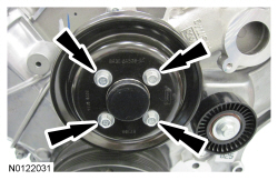
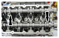
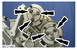
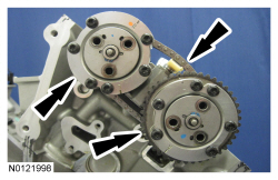
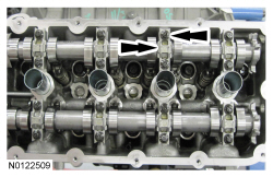
NOTICE: The front camshaft bearing mega cap must be removed first and then the remaining camshaft bearing caps. Failure to follow this direction may result in damage to the engine.
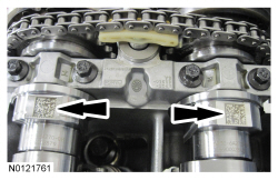
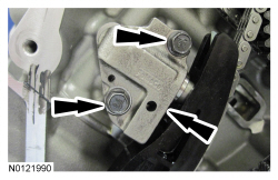
Remove the 4 bolts and the RH front camshaft bearing mega cap.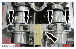
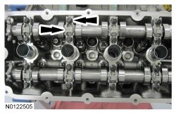
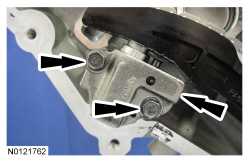
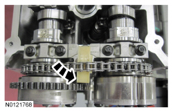
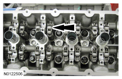
NOTE: Intake camshaft shown, exhaust camshaft similar.
Remove the VCT system oil filter from the intake and exhaust camshafts.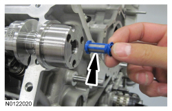
NOTICE: The cylinder head must be cool before removing it from the engine. Cylinder head warpage can result if a warm or hot cylinder head is removed.
NOTICE: Place clean shop towels over exposed engine cavities. Carefully remove the towels so foreign material is not dropped into the engine.
NOTICE: The cylinder head bolts must be discarded and new bolts must be installed. They are a tighten-to-yield design and cannot be reused.
NOTICE: Do not use metal scrapers, wire brushes, power abrasive discs or other abrasive means to clean the sealing surfaces. These tools cause scratches and gouges that make leak paths. Use a plastic scraping tool to remove all traces of the head gasket.
NOTICE: Aluminum surfaces are soft and can be scratched easily. Never place the cylinder head gasket surface, unprotected, on a bench surface.
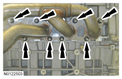
Remove the 10 bolts and the RH cylinder head.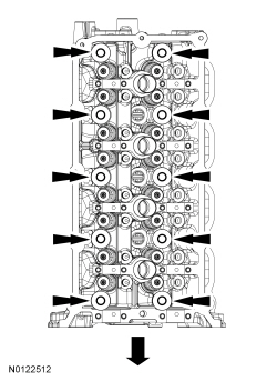
NOTICE: Do not use metal scrapers, wire brushes, power abrasive discs or other abrasive means to clean the sealing surfaces. These tools cause scratches and gouges that make leak paths. Use a plastic scraping tool to remove all traces of the head gasket.
NOTE: Observe all warnings or notices and follow all application directions contained on the packaging of the silicone gasket remover and the metal surface prep.
NOTE: If there is no residual gasket material present, metal surface prep can be used to clean and prepare the surfaces.
Clean the cylinder head-to-cylinder block mating surfaces of both the cylinder head and the cylinder block in the following sequence.NOTE: Make sure all cylinder head surfaces are clear of any gasket material, RTV, oil and coolant. The cylinder head surface must be clean and dry before running a flatness check.
NOTE: Use a straightedge that is calibrated by the manufacturer to be flat within 0.005 mm (0.0002 in) per running foot length. For example, if the straightedge is 61 cm (24 in) long, the machined edge must be flat within 0.010 mm (0.0004 in) from end to end.
Support the cylinder head on a bench with the head gasket side up. Check the cylinder head distortion and the cylinder block distortion, paying particular attention to the oil pressure feed area. For additional information, refer to Section 303-00 .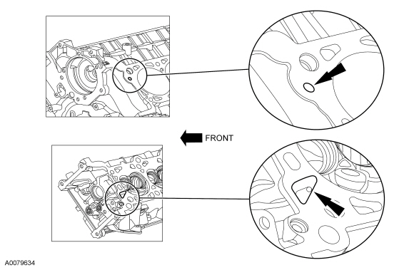
NOTE: It may be necessary to rotate the crankshaft slightly to provide enough slack in the chain to remove the LH timing chain tensioner arm. Return the crankshaft keyway to the 9 o'clock position after removing the LH timing chain tensioner arm.
Remove the LH timing chain tensioner arm.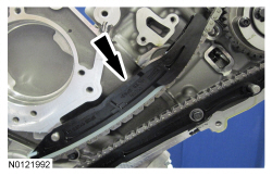
NOTE: It may be necessary to rotate the crankshaft slightly to provide enough slack in the chain to remove the LH timing chain guide. Return the crankshaft keyway to the 9 o'clock position after removing the LH timing chain guide.
Remove the bolt and the LH timing chain guide.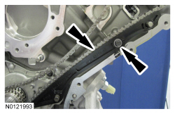

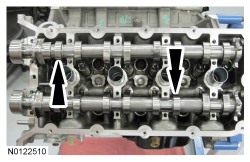
NOTICE: The front camshaft bearing mega cap must be removed first and then the remaining camshaft bearing caps. Failure to follow this direction may result in damage to the engine.
Remove the 4 bolts and the LH front camshaft bearing mega cap.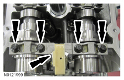
NOTE: Intake camshaft shown, exhaust camshaft similar.
Remove the VCT system oil filter from the intake and exhaust camshafts.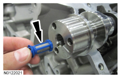

NOTICE: The cylinder head must be cool before removing it from the engine. Cylinder head warpage can result if a warm or hot cylinder head is removed.
NOTICE: Place clean shop towels over exposed engine cavities. Carefully remove the towels so foreign material is not dropped into the engine.
NOTICE: The cylinder head bolts must be discarded and new bolts must be installed. They are a tighten-to-yield design and cannot be reused.
NOTICE: Do not use metal scrapers, wire brushes, power abrasive discs or other abrasive means to clean the sealing surfaces. These tools cause scratches and gouges that make leak paths. Use a plastic scraping tool to remove all traces of the head gasket.
NOTICE: Aluminum surfaces are soft and can be scratched easily. Never place the cylinder head gasket surface, unprotected, on a bench surface.
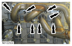
Remove the 10 bolts and the LH cylinder head.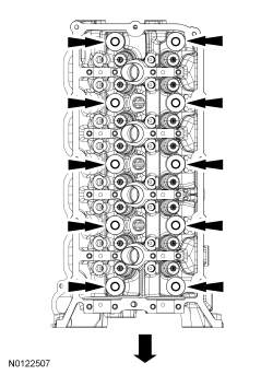
NOTICE: Do not use metal scrapers, wire brushes, power abrasive discs or other abrasive means to clean the sealing surfaces. These tools cause scratches and gouges that make leak paths. Use a plastic scraping tool to remove all traces of the head gasket.
NOTE: Observe all warnings or notices and follow all application directions contained on the packaging of the silicone gasket remover and the metal surface prep.
NOTE: If there is no residual gasket material present, metal surface prep can be used to clean and prepare the surfaces.
Clean the cylinder head-to-cylinder block mating surfaces of both the cylinder head and the cylinder block in the following sequence.NOTE: Make sure all cylinder head surfaces are clear of any gasket material, RTV, oil and coolant. The cylinder head surface must be clean and dry before running a flatness check.
NOTE: Use a straightedge that is calibrated by the manufacturer to be flat within 0.005 mm (0.0002 in) per running foot length. For example, if the straightedge is 61 cm (24 in) long, the machined edge must be flat within 0.010 mm (0.0004 in) from end to end.
Support the cylinder head on a bench with the head gasket side up. Check the cylinder head distortion and the cylinder block distortion, paying particular attention to the oil pressure feed area. For additional information, refer to Section 303-00 .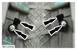
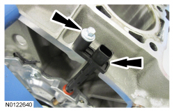
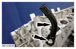
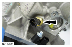
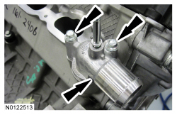
NOTICE: A new oil cooler must be installed or severe damage to the engine can occur.
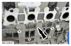
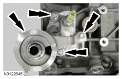
If equipped, remove the threaded fitting and the oil cooler.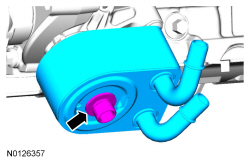
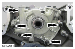
NOTICE: Do not use metal scrapers, wire brushes, power abrasive discs or other abrasive means to clean the sealing surfaces. These tools cause scratches and gouges which make leak paths. Use a plastic scraping tool to remove all traces of old sealant.
Remove the bolts and the oil pan.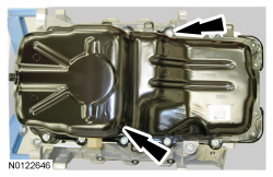

NOTICE: Do not use metal scrapers, wire brushes, power abrasive discs or other abrasive means to clean the sealing surfaces. These tools cause scratches and gouges which make leak paths. Use a plastic scraping tool to remove all traces of old sealant.
Clean and inspect the sealing surfaces.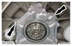
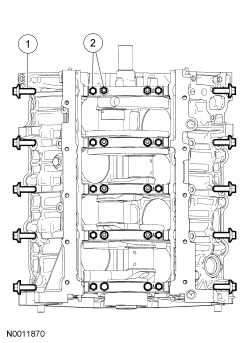
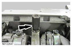
NOTICE: Verify that the connecting rod and rod cap have orientation numbers cast into them. If not, number the connecting rod and rod cap for correct orientation. Failure to do so can result in engine damage.
Remove the bolts and the connecting rod cap. Discard the bolts.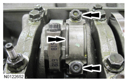
NOTICE: Do not scratch the cylinder walls or crankshaft journals with the connecting rod or engine damage may occur.
Use the Connecting Rod Installer to push the piston through the top of the cylinder block.