303-1040 (SR-015486)

205-153 (T80T-4000-W)

303-448 (T93P-6303-A)

205-142 (T80T-4000-J)

303-335 (T88T-6701-A2 plate only)

303-1531

303-1247/2

303-D055 (D85L-6000-A) or equivalent
SECTION 303-01B: Engine — 5.0L (4V)
| 2014 Mustang Workshop Manual
|
INSTALLATION
| Procedure revision date: 01/07/2013
|
| Alignment Pins, Cylinder Head
303-1040 (SR-015486) |
| Handle
205-153 (T80T-4000-W) |
| Holding Tool, Crankshaft
303-448 (T93P-6303-A) |
| Installer, Differential Bearing Cone
205-142 (T80T-4000-J) |
| Installer, Front Cover Oil Seal
303-335 (T88T-6701-A2 plate only) |
| Installer, Front Crank Seal and Damper
303-1531 |
| Installer, Spark Plug Tube Seal
303-1247/2 |
| Strap Wrench
303-D055 (D85L-6000-A) or equivalent |
| Item | Specification |
|---|---|
| Motorcraft® Metal Surface Prep
ZC-31-A | — |
| Motorcraft® SAE 5W-20 Premium Synthetic Blend Motor Oil (US); Motorcraft® SAE 5W-20 Super Premium Motor Oil (Canada)
XO-5W20-QSP (US); CXO-5W20-LSP12 (Canada) | WSS-M2C945-A |
| Motorcraft® Silicone Gasket Remover
ZC-30 | — |
| Motorcraft® Orange Antifreeze/Coolant Concentrated
VC-3-B (US); CVC-3-B2 (Canada) | WSS-M97B44-D |
| Motorcraft® Silicone Brake Caliper Grease and Dielectric Compound
XG-3-A | ESE-M1C171-A |
| Motorcraft® Silicone Gasket and Sealant
TA-30 | WSE-M4G323-A4 |
Installation
All cylinder heads
NOTICE: Make sure all coolant residue and foreign material are cleaned from the block surface and cylinder bore. Failure to follow these instructions may result in engine damage.
NOTICE: The use of sealing aids (aviation cement, copper spray and glue) is not permitted. The gasket must be installed dry. Failure to follow these instructions may result in future oil leakage.
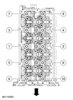
NOTICE: The cylinder head bolts must be discarded and new bolts installed. They are a tighten-to-yield design and cannot be reused.
NOTE: Do not turn the crankshaft until instructed to do so.
NOTE: LH shown, RH similar.
Using the Cylinder Head Alignment Pins, position the cylinder head gaskets and cylinder heads over the dowels and install the cylinder head bolts loosely.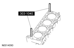
RH cylinder head
NOTICE: Do not use metal scrapers, wire brushes, power abrasive discs or other abrasive means to clean the sealing surfaces. These tools cause scratches and gouges which make leak paths. Use a plastic scraper to clean the sealing surfaces.
Clean the exhaust manifold mating surface of the cylinder head with metal surface prep. Follow the directions on the packaging.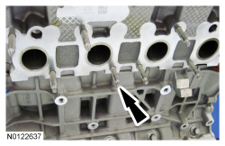
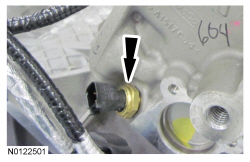
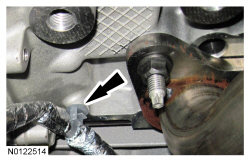
NOTICE: Lubricate the O-ring seal with clean engine coolant prior to installing.
Using a new O-ring seal, install the coolant outlet pipe.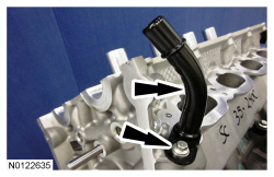
LH cylinder head
NOTICE: Do not use metal scrapers, wire brushes, power abrasive discs or other abrasive means to clean the sealing surfaces. These tools cause scratches and gouges which make leak paths. Use a plastic scraper to clean the sealing surfaces.
Clean the exhaust manifold mating surface of the cylinder head with metal surface prep. Follow the directions on the packaging.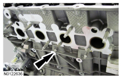
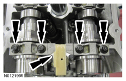
NOTE: Lubricate the camshaft roller follower and hydraulic lash adjuster assemblies with clean engine oil prior to installation.
Install the 16 camshaft roller follower and hydraulic lash adjuster assemblies.
NOTE: Lubricate the camshafts with clean engine oil prior to installation.
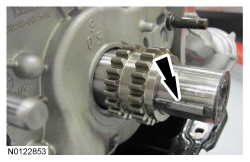
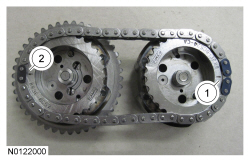
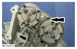
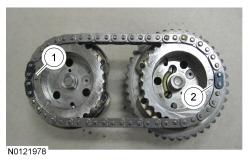
Install the LH intake and exhaust camshafts in the neutral position. Align the D-slots as shown in the illustration.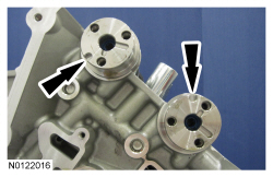
NOTE: Intake camshaft shown, exhaust camshaft similar.
Install the Variable Camshaft Timing (VCT) system oil filter in the intake and exhaust camshafts.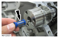
NOTE: It may be necessary to rotate the exhaust camshaft slightly (using a wrench on the flats of the camshaft) to seat the VCT assemblies onto the camshafts.
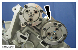
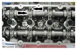
Rotate the secondary timing chain tensioner 90 degrees so the ramped area is facing forward and fully seat the VCT assemblies onto the camshafts.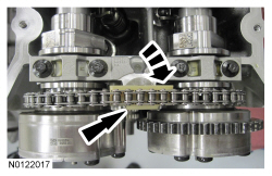
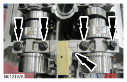
NOTE: Use a wrench on the flats of the camshaft to hold the camshafts while tightening the VCT assembly bolts.
Install the 3 LH intake VCT assembly bolts and the 3 LH exhaust VCT assembly bolts.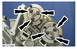
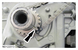
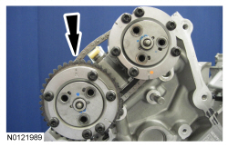
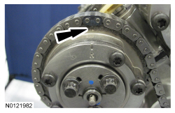
NOTE: It may be necessary to rotate the crankshaft slightly to provide enough slack in the chain to install the LH timing chain guide. Return the crankshaft keyway to the 9 o'clock position after installing the LH timing chain guide.
Install the LH timing chain guide and bolt.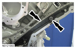
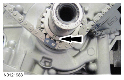
NOTE: It may be necessary to rotate the crankshaft slightly to provide enough slack in the chain to install the LH timing chain tensioner arm. Return the crankshaft keyway to the 9 o'clock position after installing the LH timing chain tensioner arm.
Install the LH timing chain tensioner arm.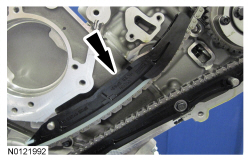
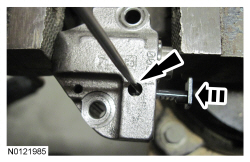
NOTE: Complete the following 3 steps on both the LH and RH primary timing chain tensioners.
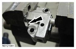
NOTICE: Do not compress the ratchet assembly or damage to the tensioner will occur.
Compress the primary timing chain tensioner plunger, using an edge of a vise.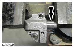
RH cylinder head
NOTE: Lubricate the camshaft roller follower and hydraulic lash adjuster assemblies with clean engine oil prior to installation.
Install the 16 camshaft roller follower and hydraulic lash adjuster assemblies.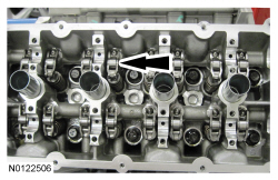
NOTE: Lubricate the camshafts with clean engine oil prior to installation.
Install the RH intake and exhaust camshafts in the neutral position. Align the D-slots as shown in the illustration.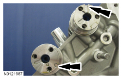
NOTE: Intake camshaft shown, exhaust camshaft similar.
Install the VCT system oil filter in the intake and exhaust camshafts.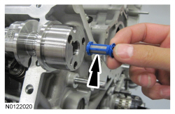
NOTE: It may be necessary to rotate the exhaust camshaft slightly (using a wrench on the flats of the camshaft) to seat the VCT assemblies onto the camshafts.
Rotate the secondary timing chain tensioner 90 degrees so the ramped area is facing forward and fully seat the VCT assemblies onto the camshafts.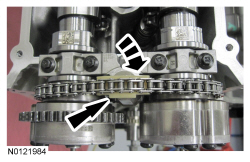
NOTE: Use a wrench on the flats of the camshaft to hold the camshafts while tightening the VCT assembly bolts.
Install the 3 RH intake VCT assembly bolts and the 3 RH exhaust VCT assembly bolts.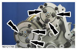
All cylinder heads
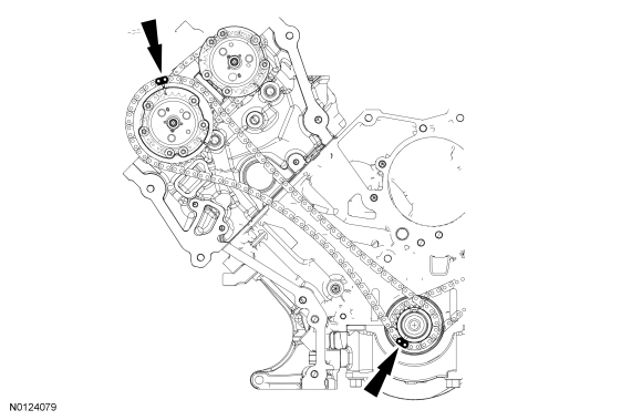
NOTE: It may be necessary to rotate the crankshaft slightly to provide enough slack in the chain to install the RH timing chain guide. Return the crankshaft keyway to the 12 o'clock position after installing the RH timing chain guide.
Install the RH timing chain guide and bolt.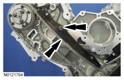
NOTE: It may be necessary to rotate the crankshaft slightly to provide enough slack in the chain to install the RH timing chain tensioner arm. Return the crankshaft keyway to the 12 o'clock position after installing the RH timing chain tensioner arm.
Install the RH timing chain tensioner arm.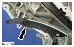
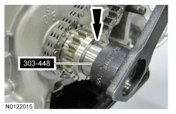
NOTICE: The Variable Camshaft Timing (VCT) variable force solenoid pins must be fully depressed to avoid interference with the VCT valve tips when installing the engine front cover. Failure to follow these instructions can result in damage to the engine.
NOTE: LH shown, RH similar.
Fully depress the VCT variable force solenoid pins.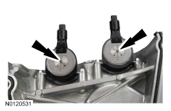
NOTE: The engine front cover must be installed and all fasteners final tightened within 5 minutes of applying the sealer. If this cannot be accomplished, install the engine front cover and tighten fasteners 6, 7, 8, 9, 10 and 11 to 8 Nm (71 lb-in) within 5 minutes of applying the sealer. All of the fasteners must then be final tightened within 1 hour of applying the sealer. If this time limit is exceeded, all sealant must be removed and the sealing area cleaned. To clean the sealing area, use silicone gasket remover and metal surface prep. Follow the directions on the packaging. Failure to follow this procedure can cause future oil leakage.
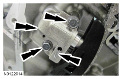
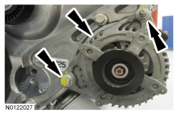
Apply a bead of silicone gasket and sealant to the cylinder head-to-cylinder block joints and the oil pan-to-cylinder block joints as illustrated.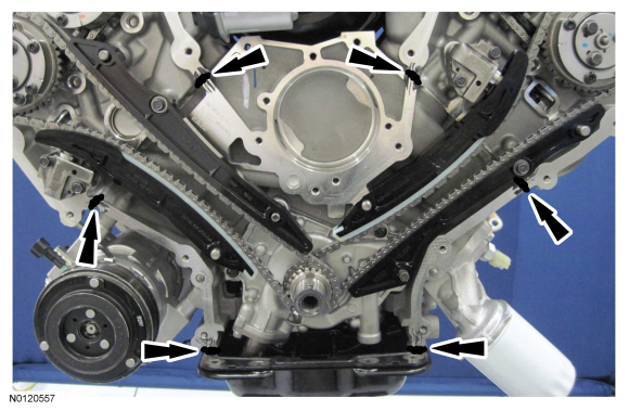
NOTE: Make sure that the engine front cover gasket is in place on the engine front cover before installation.
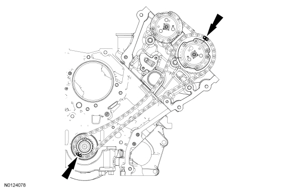
Using new gaskets, position the engine front cover onto the dowels.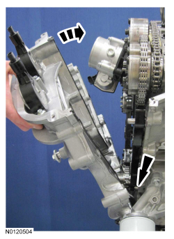
NOTE: The engine front cover must be installed and all fasteners final tightened within 5 minutes of applying the sealer. If this cannot be accomplished, install the engine front cover and tighten fasteners 6, 7, 8, 9, 10 and 11 to 8 Nm (71 lb-in) within 5 minutes of applying the sealer. All of the fasteners must then be final tightened within 1 hour of applying the sealer. If this time limit is exceeded, all sealant must be removed and the sealing area cleaned. To clean the sealing area, use silicone gasket remover and metal surface prep. Follow the directions on the packaging. Failure to follow this procedure can cause future oil leakage.
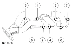
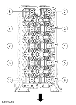
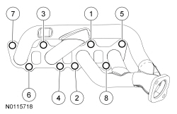
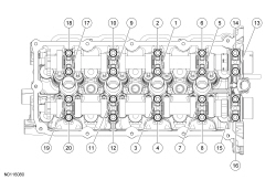
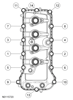
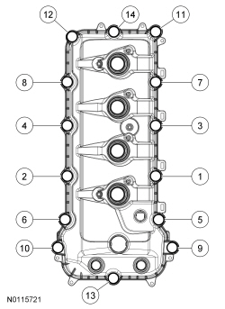
Tighten the bolts in the sequence shown in 2 stages.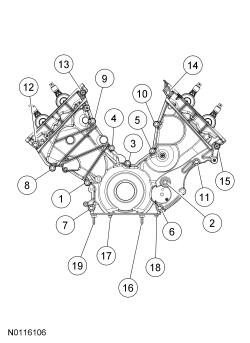
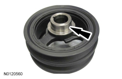
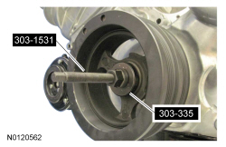
NOTE: Lubricate the engine front cover bore and the crankshaft front oil seal inner lip with clean engine oil.
Using the Front Crank Seal and Damper Installer and the Front Cover Oil Seal Installer (plate only), install the crankshaft front oil seal.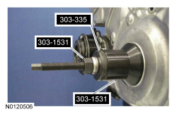
NOTE: If not secured within 5 minutes, the sealant must be removed and the sealing area cleaned with silicone gasket remover and metal surface prep. Failure to follow this procedure can cause future oil leakage.
Apply silicone gasket and sealant to the Woodruff key slot in the crankshaft pulley.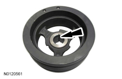

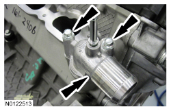
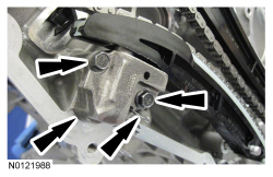
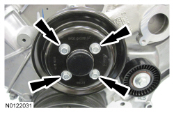
NOTE: Lubricate the new coolant pump O-ring seal with clean engine coolant.
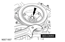
Using a new O-ring seal, install the coolant pump and the 4 bolts.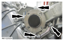
NOTE: Installation of new seals is only required if damaged seals were removed.
Using the VCT Spark Plug Tube Seal Installer and Handle, install new spark plug tube seals.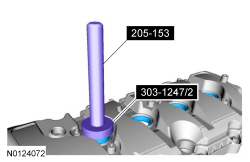
NOTE: Installation of new seals is only required if damaged seals were removed.
Using the Differential Bearing Cone Installer and Handle, install new VCT variable force solenoid seal(s).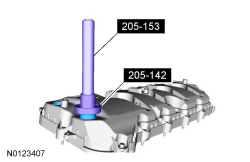
NOTE: If the valve cover is not installed and the fasteners tightened within 5 minutes, the sealant must be removed and the sealing area cleaned. To clean the sealing area, use silicone gasket remover and metal surface prep. Failure to follow this procedure can cause future oil leakage.
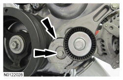
Apply an 8 mm (0.31 in) bead of silicone gasket and sealant to the engine front cover-to-LH cylinder head joints.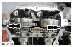
NOTE: Installation of new seals is only required if damaged seals were removed.
Using the VCT Spark Plug Tube Seal Installer and Handle, install new spark plug tube seals.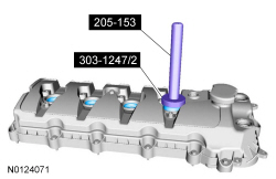
NOTE: Installation of new seals is only required if damaged seals were removed.
Using the Differential Bearing Cone Installer and Handle, install new VCT variable force solenoid seal(s).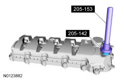
NOTE: If the valve cover is not installed and the fasteners tightened within 5 minutes, the sealant must be removed and the sealing area cleaned. To clean the sealing area, use silicone gasket remover and metal surface prep. Failure to follow this procedure can cause future oil leakage.
Apply an 8 mm (0.31 in) bead of silicone gasket and sealant to the engine front cover-to-RH cylinder head joints.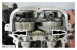
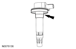
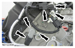
NOTE: Apply a small amount of dielectric grease to the inside of the ignition coil-on-plug boots before attaching to the spark plugs. RH shown, LH similar.
Install the 8 ignition coils and 8 bolts.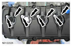
NOTE: RH shown, LH similar.
Attach the 9 wiring harness retainers to the RH valve cover and the 10 wiring harness retainers to the LH valve cover.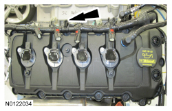
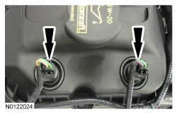
NOTE: RH shown, LH similar.
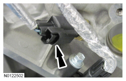
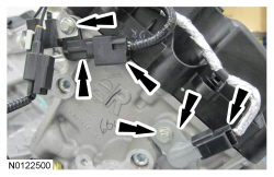
Connect the 8 ignition coil electrical connectors.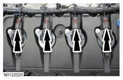
NOTE: RH shown, LH similar.
Connect the 4 VCT variable force solenoid electrical connectors.