SECTION 303-01B: Engine — 5.0L (4V)
| 2014 Mustang Workshop Manual
|
INSTALLATION
| Procedure revision date: 01/07/2013
|
Engine — Automatic Transmission
Special Tool(s)
 | Heavy Duty Floor Crane
014-00071 or equivalent
|
 | Lifting Bracket, Engine
303-F047 (014-00073) or equivalent
|
 | Retainer, Torque Converter
307-346 (T97T-7902-A) or equivalent
|
 | Support Bar, Engine
303-F072
|
 | Vehicle Communication Module (VCM) and Integrated Diagnostic System (IDS) software with appropriate hardware, or equivalent scan tool
|
Material
| Item
| Specification
|
|---|
Motorcraft® SAE 5W-20 Premium Synthetic Blend Motor Oil (US); Motorcraft® SAE 5W-20 Super Premium Motor Oil (Canada)
XO-5W20-QSP (US); CXO-5W20-LSP12 (Canada)
| WSS-M2C945-A
|
Motorcraft® Multi-Purpose Grease
XL-5
| ESB-M1C93-B
|
 WARNING: Do not smoke, carry lighted tobacco or have an open flame of any type when working on or near any fuel-related component. Highly flammable mixtures are always present and may be ignited. Failure to follow these instructions may result in serious personal injury.
WARNING: Before working on or disconnecting any of the fuel tubes or fuel system components, relieve the fuel system pressure to prevent accidental spraying of fuel. Fuel in the fuel system remains under high pressure, even when the engine is not running. Failure to follow this instruction may result in serious personal injury.
NOTICE:
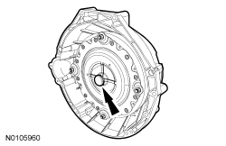
Prior to installation of the engine, the torque converter pilot hub must be lubricated with multi-purpose grease or damage to the torque converter or the engine crankshaft can occur.
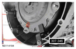
Lubricate the torque converter pilot hub with multi-purpose grease.
- Remove the Torque Converter Retainer.
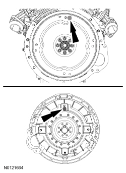
- Align the torque converter stud and flexplate hole near the paint marks at the 12 o'clock position.
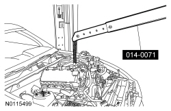
- Using the Heavy Duty Floor Crane and the Engine Lifting Bracket, install the engine into the vehicle.
NOTE:
Do not tighten the bolt at this time.
Install the transmission-to-engine bolt.
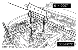
NOTICE:
Do not position the legs of the Engine Support Bar on the fenders. Instead, the legs should be positioned on the body structure near the suspension strut tower. Failure to follow these instructions may result in body damage.
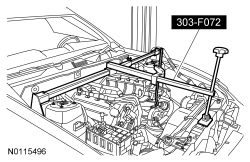
Install the Engine Support Bar.
- Attach the Engine Support Bar to the through bolt on the Engine Lifting Bracket.
- Once the engine is supported by the Engine Support Bar remove the Heavy Duty Floor Crane.
- Using the Engine Support Bar, level the engine in the vehicle.
NOTE:
Do not tighten the bolts at this time.
Install the 2 LH transmission-to-engine bolts.
- Install 2 RH transmission-to-engine bolts.
- Tighten the 5 installed transmission-to-engine bolts to 48 Nm (35 lb-ft).
- Install 4 new torque converter nuts.
- Tighten to 40 Nm (30 lb-ft).
- Install the rubber access plug.
- Install the flexplate inspection cover, the bolt, and the stud bolt.
- Tighten to 35 Nm (26 lb-ft).
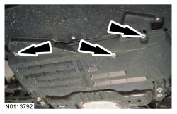
- Remove the 3 bolts and lower the underbody shield.
- Install the A/C compressor and the 3 stud bolts.
- Tighten to 25 Nm (18 lb-ft).
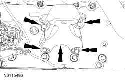
NOTE:
The engine support insulator bracket must be positioned on the engine support insulator stud. If necessary, adjust the height of the engine using the engine support bar.
Install the LH engine support insulator bracket, the 3 bolts and the stud bolt.
- Tighten to 55 Nm (41 lb-ft).
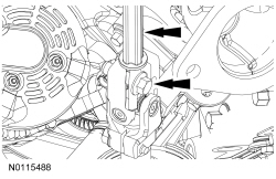
- Position the steering intermediate shaft and install the bolt.
- Tighten to 47 Nm (35 lb-ft).
NOTE:
The engine support insulator bracket must be positioned on the engine support insulator stud. If necessary, adjust the height of the engine using the engine support bar.
Install the RH engine support insulator bracket, the 2 bolts and the 2 stud bolts.
- Tighten to 55 Nm (41 lb-ft).
- Install the ground strap and the nut to the RH engine support insulator bracket.
- Tighten to 48 Nm (35 lb-ft).
- Attach the wiring harness retainers to A/C compressor stud bolts and the RH side of the oil pan.
- Attach the wiring harness retainers to the RH side of the oil pan and the RH engine support insulator bracket stud bolt.
- Install the transmission cooler tube clamp and nut to the RH engine support insulator bracket.
- Tighten to 48 Nm (35 lb-ft).
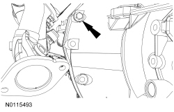
- Install the transmission fluid cooler tube bracket and nut to the flexplate inspection cover stud bolt.
- Tighten to 13 Nm (115 lb-in).
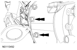
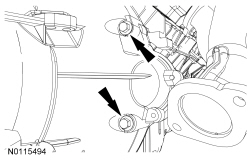
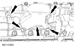
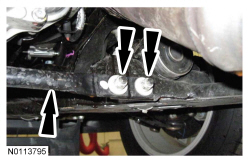
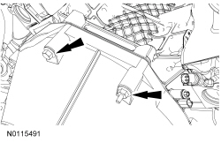
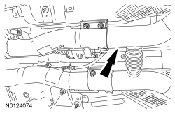
- Install the front crossmember brace and the 4 nuts (2 shown).
- Tighten to 48 Nm (35 lb-ft).
- Install the lower radiator sight shield and the 9 screws.
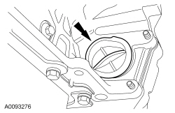
- Using the Engine Support Bar, lower the engine onto the engine support insulators.
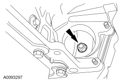
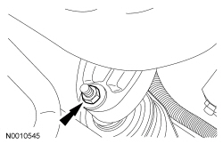
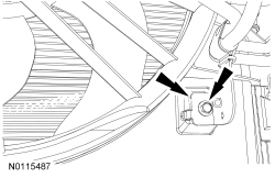
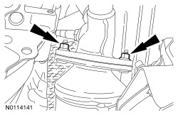
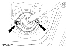
NOTE:
RH shown, LH similar.
Install the RH and LH engine support insulator nuts.
- Tighten to 63 Nm (46 lb-ft).
- Remove the Engine Support Bar and the Engine Lifting Bracket.
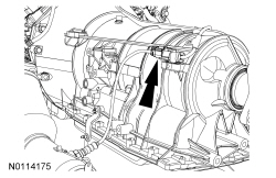
- Install the top transmission-to-engine bolt and stud bolt.
- Tighten to 48 Nm (35 lb-ft).
- Install the A/C belt and the accessory drive belt. For additional information, refer to
Section 303-05
.
- Install the transmission cooler tube clamp bolt to the fan shroud.
- Tighten to 8 Nm (71 lb-in).
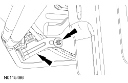
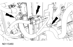
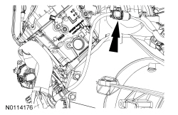
- Connect the middle PCM electrical connector, the 16 pin electrical connector and attach the wiring harness retainers to the PCM bracket.
- Attach the wiring harness retainers to the LH side of the oil pan and the front oil pan stud bolts and install the 2 nuts.
- Tighten to 8 Nm (71 lb-in).
- Position the underbody shield and install the 3 bolts.
- Tighten to 10 Nm (89 lb-in).
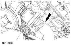
- Install the starter motor. For additional information, refer to
Section 303-06
.
NOTE:
Use a jackstand to support the exhaust H-pipe in place.
NOTE:
Do not tighten the H-pipe clamp nuts at this time.
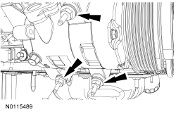
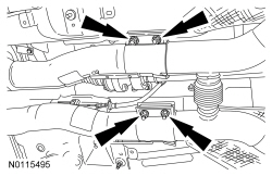
Using new gaskets, position the catalytic converter/H-pipe assembly.
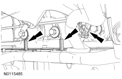
NOTE:
Tighten the catalytic converter-to-exhaust manifold nuts alternately in 10 Nm (89 lb-in) increments to maintain torque and draw flange evenly to assure alignment of the exhaust system.
Install 2 new LH catalytic converter-to-exhaust manifold nuts.
- Tighten to 40 Nm (30 lb-ft).
NOTE:
Tighten the catalytic converter-to-exhaust manifold nuts alternately in 10 Nm (89 lb-in) increments to maintain torque and draw flange evenly to assure alignment of the exhaust system.
Install 2 new RH catalytic converter-to-exhaust manifold nuts.
- Tighten to 40 Nm (30 lb-ft).
- Tighten the H-pipe clamp nuts to 48 Nm (35 lb-ft).
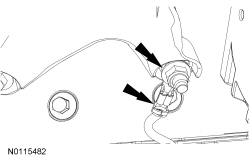
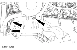
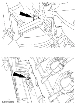
NOTE:
LH shown, RH similar.
Connect the LH and RH Catalyst Monitor Sensor (CMS) electrical connectors.
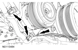
NOTE:
LH shown, RH similar.
Connect the LH and RH Heated Oxygen Sensor (HO2S) sensor electrical connectors.
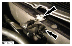
- Install the B+ cable, the nut, and the electrical connector to the generator.
- Tighten to 17 Nm (150 lb-in).
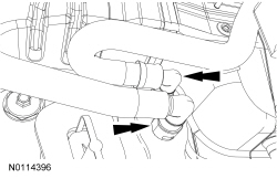
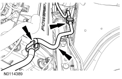
- Connect the 2 heater hose quick connect couplings to the heater core. For additional information, refer to
Section 412-00
.
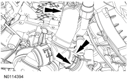
- Connect the lower radiator hose to the engine.
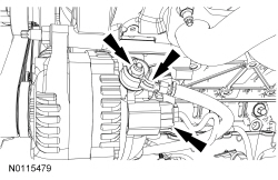
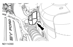
- Connect the coolant bypass T assembly to the engine and install the clamp and the spring clip.
- Install the Air Cleaner (ACL) inlet pipe.
- Install the battery tray. For additional information, refer to
Section 414-01
.
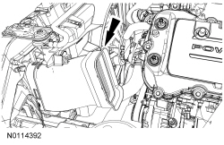
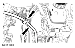
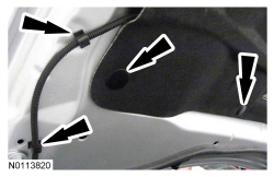
- Attach the EVAP tube to the LH valve cover and the LH inner fender.
- Attach the fuel supply tube to the LH valve cover.
- Install the intake manifold. For additional information, refer to
Intake Manifold
in this section.
- Install the degas bottle. For additional information, refer to
Section 303-03A
.
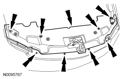
- Install the upper radiator sight shield and the 8 pin-type retainers.
- Attach the sound enhancement pipe retainer.
- Install the
outlet pipe and the
. For additional information, refer to the exploded view in
Section 303-12
.
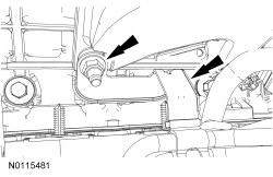
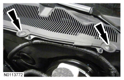
- Lift the cowl screen and install the ground strap bolt.
- Tighten to 10 Nm (89 lb-in).
- Attach the wiring harness retainer to the cowl.
- Install the 2 cowl vent screen plastic rivets.
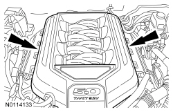
NOTE:
The engine appearance cover rubber grommets may remain on the cover. If so, remove the grommets from the cover and install them on the intake manifold before installing the cover.
Install the engine appearance cover.
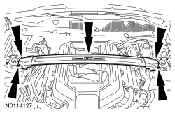
- If equipped, install the strut tower cross brace and the 4 nuts.
- Tighten to 35 Nm (26 lb-ft).
NOTE:
Use the hood hinge location index marks made during removal to aid in hood installation.
Install the hood and the 4 bolts.
- Tighten to 12 Nm (106 lb-in).
- Attach the 2 windshield washer hose retainers and connect the 2 windshield washer hose C-Lock Couplers. For additional information, refer to
Section 501-16
.
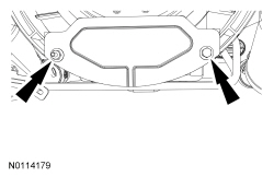
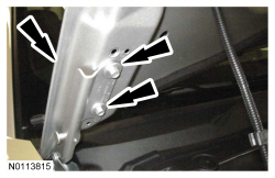
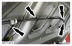
- Install the 2 windshield washer hose retainers and the 8 hood insulation pin-type retainers (2 shown).
- Install the 2 steering column dash boot nuts.
- Tighten to 9 Nm (80 lb-in).
- Fill the engine with clean engine oil.
- Connect the battery ground cable. For additional information, refer to
Section 414-01
.
- Fill and bleed the engine cooling system. For additional information, refer to
Section 303-03A
.
- After completing the repairs, use the scan tool to perform the Misfire Monitor Neutral Profile Correction procedure, following the on-screen instructions.