SECTION 303-01C: Engine — 5.8L (4V)
| 2014 Mustang Workshop Manual
|
IN-VEHICLE REPAIR
| Procedure revision date: 01/07/2013
|
Oil Filter Adapter
Special Tool(s)
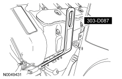
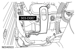
 | Lifting Bracket, Engine (2 required)
303-D087 (D93P-6001-A1) or equivalent
|
 | Support Bar, Engine
303-F070
|
 | Support Bar, Engine
303-F072
|
Material
| Item
| Specification
|
|---|
Motorcraft® Metal Surface Prep
ZC-31-A
| —
|
Motorcraft® SAE 5W-50 Full Synthetic Motor Oil
XO-5W50-QGT
| WSS-M2C931-B
|
Removal
Alll vehicles
- With the vehicle in NEUTRAL, position it on a hoist. Refer to
Section 100-02
.
- Remove the 2 dash boot nuts.
NOTE:
Use a steering wheel holding device (such as Hunter® 28-75-1 or equivalent).
Using a suitable holding device, hold the steering wheel in the straight-ahead position.
- Remove the Air Cleaner (ACL) assembly and
outlet pipe. Refer to
Section 303-12
.
- Remove the battery and tray. Refer to
Section 414-01
.
Vehicles without the cooling package
- Drain the engine cooling system. Refer to
Section 303-03A
.
- Remove the oil cooler. Refer to
Oil Cooler — Engine Mounted
.
Vehicles with the cooling package
- Remove the generator. Refer to
Section 414-00
- Remove the oil cooler thermostat. Refer to
Oil Cooler Thermostat
.
All vehicles
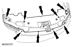
- Remove the 8 pin-type retainers and the upper radiator sight shield.
- Install the Engine Lifting Bracket.
- Install the Engine Lifting Bracket.
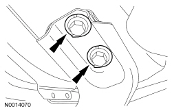
NOTE:
LH side shown, RH side similar.
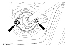
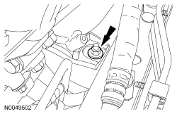
Remove the LH and RH engine support insulator nuts.
NOTE:
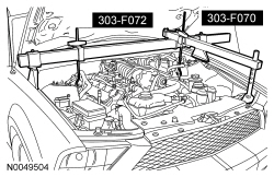
The heavy duty Engine Support Bar (303-F070) must be used with the draw screws from the light duty Engine Support Bar (303-F072). This will provide enough clearance between the Supercharger (SC) and the Engine Support Bar, and enough clearance between the draw screw and the vehicle hood.
Install the Engine Support Bars and raise the engine.
- Drain the engine oil.
- Tighten the drain plug to 26 Nm (19 lb-ft).
- Remove and discard the engine oil filter.
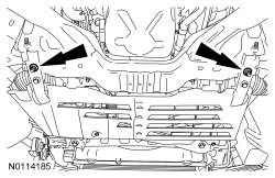
- Remove the 4 nuts and the rear subframe cross brace.
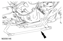
- Remove the 9 screws and the lower air deflector.
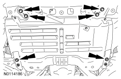
- Loosen the 2 crossmember brace nuts.
- Remove the 6 bolts and remove the crossmember brace.
- Position a suitable adjustable jackstand under the subframe.
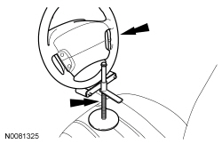
NOTICE:
Do not allow the steering wheel to rotate while the steering column intermediate shaft is disconnected or damage to the clockspring can result. If there is evidence that the wheel has rotated, the clockspring must be removed and recentered. For additional information, refer to
Section 501-20B
.
Remove the upper bolt from the intermediate steering shaft.
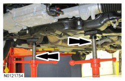
- Mark the position of the 4 subframe nuts and 4 subframe bolts for referencing during assembly.
- Remove the 4 subframe nuts and 4 subframe bolts.
- Using the adjustable jackstand, lower the subframe 100 mm (3.937 in).
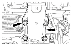
- Remove the 4 bolts and the LH engine support bracket.
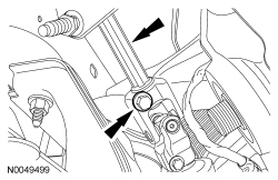
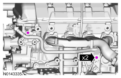
- Remove the 2 coolant tube assembly-to-oil filter adapter bolts.
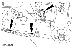
- Disconnect the Engine Oil Pressure (EOP) switch electrical connector and the 2 wiring harness pin-type retainers.
Vehicles without the cooling package
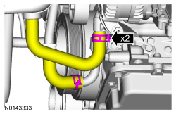
- Disconnect the 2 coolant hoses from the oil filter adapter.
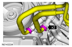
Vehicles with the cooling package
- Remove the 2 retaining clips and disconnect the 2 oil hoses from the oil filter adapter.
All vehicles
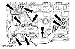
- Remove the 8 bolts and the oil filter adapter.
Installation
All vehicles
NOTE:
Clean and inspect the sealing surfaces with metal surface prep. Follow the directions on the packaging.
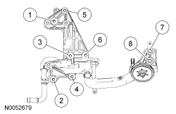
Using a new gasket, install the oil filter adapter and the 8 bolts. Tighten in the sequence shown in 2 stages.
- Stage 1: Tighten bolts 1 through 6 to 25 Nm (18 lb-ft).
- Stage 2: Tighten bolts 7 and 8 to 48 Nm (35 lb-ft).
Vehicles with the cooling package
- Connect the 2 oil hoses to the oil filter adapter and install the 2 retaining clips.
Vehicles without the cooling package
- Connect the 2 coolant hoses to the oil filter adapter.
All vehicles
- Connect the
switch electrical connector and the 2 wiring harness pin-type retainers.
- Install the 2 coolant tube assembly-to-oil filter adapter bolts.
- Tighten to 10 Nm (89 lb-in).
- Install the LH engine support bracket and the 4 bolts.
- Tighten to 55 Nm (41 lb-ft).
- Using the adjustable jackstand, raise the subframe.
NOTICE:
Do not allow the steering wheel to rotate while the steering column intermediate shaft is disconnected or damage to the clockspring can result. If there is evidence that the wheel has rotated, the clockspring must be removed and recentered. For additional information, refer to
Section 501-20B
.
Position the intermediate steering shaft and install the upper bolt.
- Tighten to 47 Nm (35 lb-ft).
NOTE:
Do not tighten the subframe nuts and bolts at this time.
Install the 4 subframe nuts and 4 subframe bolts.
- Align the subframe nuts and bolts with the reference marks made during removal.
- Tighten the nuts to 115 Nm (85 lb-ft).
- Tighten the bolts to 115 Nm (85 lb-ft).
- Install the crossmember brace and the 6 bolts.
- Tighten to 48 Nm (35 lb-ft).
- Tighten the 2 crossmember brace nuts.
- Tighten to 48 Nm (35 lb-ft).
- Install the lower air deflector and the 9 screws.
- Install the subframe rear cross brace and the 4 nuts.
- Tighten to 48 Nm (35 lb-ft).
- Install a new engine oil filter.
- Lubricate the oil filter gasket with clean engine oil and tighten until the seal makes contact.
- Using a suitable oil filter strap wrench, tighten the filter an additional 270 degrees.
- Using the Engine Support Bars, lower the engine onto the engine support insulators.
NOTICE:
Do not tighten the engine support insulator nuts until the full weight of the engine is on the engine insulator or damage to the engine insulator may occur.
NOTE:
LH side shown, RH side similar.
Install the LH and RH engine support insulator nuts.
- Tighten to 63 Nm (46 lb-ft).
- Install the upper radiator sight shield and the 8 pin-type retainers.
Vehicles with the cooling package
- Install the oil cooler thermostat. Refer to
Oil Cooler Thermostat
.
- Install the generator. Refer to
Section 414-00
.
Vehicles without the cooling package
- Install the oil cooler. Refer to
Oil Cooler — Engine Mounted
.
All vehicles
- Install the battery and tray. Refer to
Section 414-01
.
- Install the
assembly and
outlet pipe. Refer to
Section 303-12
.
- Install the dash boot and the 2 nuts.
- Tighten to 9 Nm (80 lb-in).
- Fill the engine with clean engine oil.
Vehicles without the cooling package
- Fill and bleed the engine cooling system. Refer to
Section 303-03A
.