SECTION 303-01C: Engine — 5.8L (4V)
| 2014 Mustang Workshop Manual
|
IN-VEHICLE REPAIR
| Procedure revision date: 01/07/2013
|
Timing Drive Components
Special Tool(s)
 | Holding Tool, Crankshaft
303-448 (T93P-6303-A)
|
Removal
NOTICE:
During engine repair procedures, cleanliness is extremely important. Any foreign material, including any material created while cleaning gasket surfaces, that enters the oil passages, coolant passages or the oil pan, can cause engine failure.
- Remove the engine front cover. For additional information, refer to
Engine Front Cover
in this section.
- Remove the camshaft roller followers. For additional information, refer to
Valve Train Components — Exploded View
and
Camshaft Roller Follower
in this section.
- Remove the crankshaft sensor ring.
- Remove the crankshaft washer.
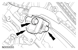
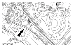
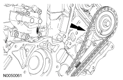
- Remove the 2 bolts and the RH primary timing chain tensioner.
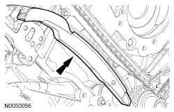
- Remove the RH primary timing chain tensioner arm.
- Remove the RH primary timing chain.
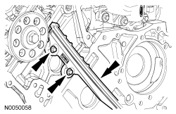
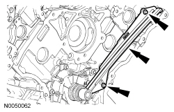
- Remove the 2 bolts and the RH primary timing chain guide.
- Remove the 2 bolts and the LH primary timing chain tensioner.
- Remove the LH primary timing chain tensioner arm.
- Remove the LH primary timing chain.
- Remove the 2 bolts and the LH primary timing chain guide.
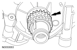
- Remove the crankshaft sprocket.
Installation
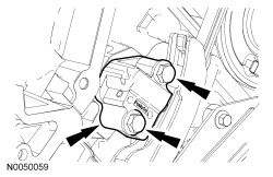
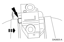
NOTICE:
Do not compress the ratchet assembly. This will damage the ratchet assembly.
NOTE:
LH shown, RH similar.
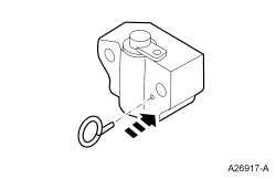
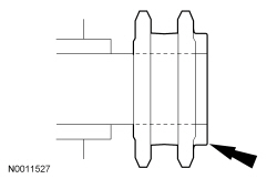
Compress each tensioner plunger, using an edge of a vise.
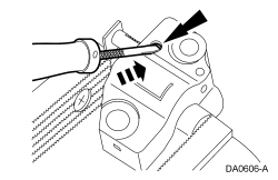
- Using a small screwdriver or pick, push back and hold the ratchet mechanism.
- While holding the ratchet mechanism, push the ratchet arm back into the tensioner housing.
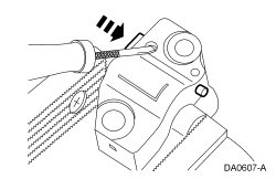
- Install a suitable pin into the hole of each tensioner housing to hold the ratchet assembly and plunger in place during installation.
- Remove the tensioner from the vise.
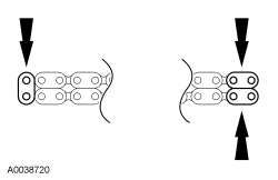
- If the colored links are not visible, mark one link on one end and 2 links on the other end, and use as timing marks.
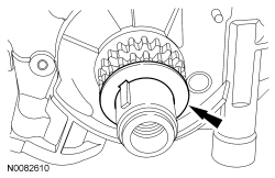
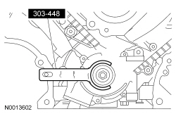
- Using the Crankshaft Holding Tool, position the crankshaft.
- Install the crankshaft sprocket with the flange facing forward.
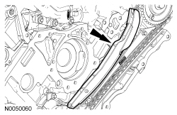
- Install the LH primary timing chain guide and the 2 bolts.
- Tighten to 10 Nm (89 lb-in).
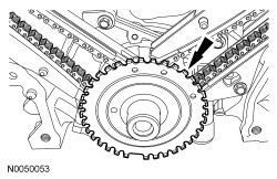
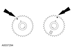
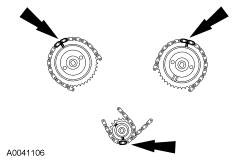
- Position the camshaft sprocket timing marks as shown.
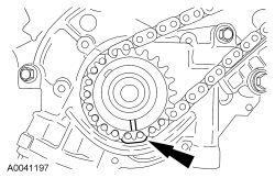
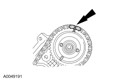
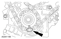
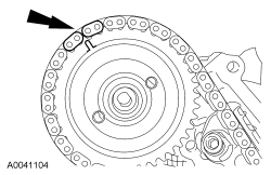
- Position the LH (inner) timing chain onto the crankshaft sprocket, aligning the one colored link on the timing chain with the slot on the crankshaft sprocket.
- Install the LH timing chain on the camshaft sprocket, aligning the 2 colored links with the timing mark on the sprocket.
- Install the LH primary timing chain tensioner arm.
- Install the LH primary timing chain tensioner and the 2 bolts.
- Tighten to 25 Nm (18 lb-ft).
- Remove the pin from the tensioner.
- Install the RH primary timing chain guide and the 2 bolts.
- Tighten to 10 Nm (89 lb-in).
- Position the RH (outer) timing chain on the crankshaft sprocket, aligning the colored link with the timing marks on the sprocket.
- Install the RH timing chain on the camshaft sprocket, aligning the 2 colored links with the timing mark on the sprocket.
- Install the RH primary timing chain tensioner arm.
- Install the RH primary timing chain tensioner and the 2 bolts.
- Tighten to 25 Nm (18 lb-ft).
- Remove the pin from the tensioner.
- As a post-check, verify correct alignment of all timing marks. Make sure that the colored links are lined up with the marks on the crankshaft sprocket and the camshaft sprockets.
- Install the crankshaft washer.
- Install the crankshaft sensor ring.
- Install the engine front cover. For additional information, refer to
Engine Front Cover
in this section.
- Install the camshaft roller followers. For additional information, refer to
Valve Train Components — Exploded View
and
Camshaft Roller Follower
in this section.