
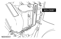
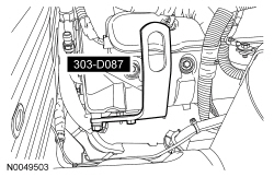
303-D087 (D93P-6001-A1) or equivalent

303-F070

303-F072

SECTION 303-01C: Engine — 5.8L (4V)
| 2014 Mustang Workshop Manual
|
IN-VEHICLE REPAIR
| Procedure revision date: 01/07/2013
|
| Lifting Bracket, Engine (2 required)
303-D087 (D93P-6001-A1) or equivalent |
| Support Bar, Engine
303-F070 |
| Support Bar, Engine
303-F072 |
| Vehicle Communication Module (VCM) and Integrated Diagnostic System (IDS) software with appropriate hardware, or equivalent scan tool
|
| Item | Specification |
|---|---|
| Motorcraft® High Performance Engine RTV Silicone
TA-357 | WSE-M4G323-A6 |
| Motorcraft® Metal Surface Prep
ZC-31-A | — |
| Motorcraft® SAE 5W-50 Full Synthetic Motor Oil
XO-5W50-QGT | WSS-M2C931-B |
| Motorcraft® Silicone Gasket Remover
ZC-30 | — |
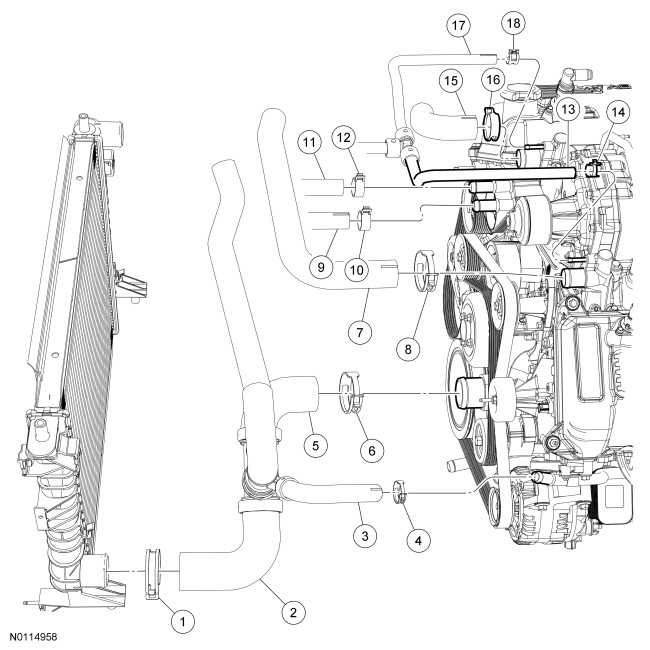
| Item | Part Number | Description |
|---|---|---|
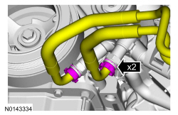
| 1 | 15161 | Lower radiator hose assembly-to-radiator clamp |
| 2 | 8B273 | Lower radiator hose assembly-to-radiator |
| 3 | 8B273 | Lower radiator hose assembly-to-coolant tube assembly |
| 4 | 15161 | Lower radiator hose assembly-to-coolant tube assembly clamp |
| 5 | 8B273 | Lower radiator hose assembly-to-coolant pump |
| 6 | 15161 | Lower radiator hose assembly-to-coolant pump clamp |
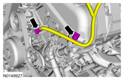
| 7 | 8A586 | Upper radiator hose |
| 8 | 15161 | Upper radiator hose clamp |
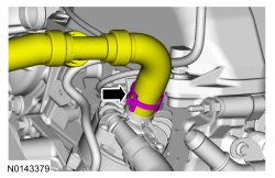
| 9 | 8D031 | Charge Air Cooler (CAC) coolant hose |
| 10 | W527362 | CAC coolant hose clamp |
| 11 | 8D030 | CAC coolant hose |
| 12 | W527362 | CAC coolant hose clamp |
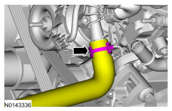
| 13 | 8276 | Coolant vent hose |
| 14 | W527352 | Coolant vent hose clamp |
| 15 | 8A586 | Upper radiator hose |
| 16 | 15161 | Upper radiator hose clamp |
| 17 | 8276 | Coolant vent hose |
| 18 | W527352 | Coolant vent hose clamp |
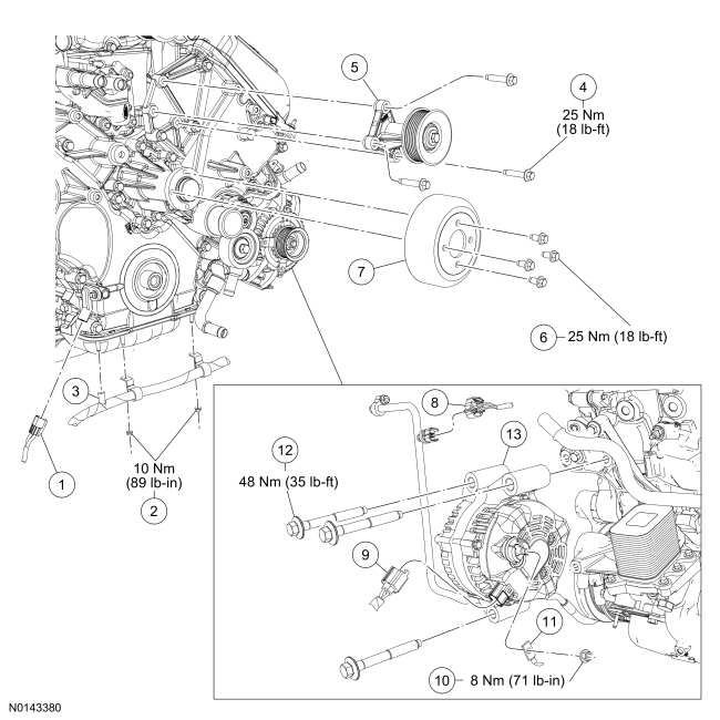
| Item | Part Number | Description |
|---|---|---|
| 1 | — | Crankshaft Position (CKP) sensor electrical connector (part of 12B637) |
| 2 | W701852 | Wire harness retainer bracket nuts |
| 3 | — | Wire harness retainer (part of 12B637) |
| 4 | W500310 | Accessory drive idler pulley and bracket bolt (3 required) |
| 5 | 6A553 | Accessory drive idler pulley and bracket assembly |
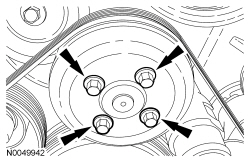
| 6 | N806282 | Coolant pump pulley bolt (4 required) |
| 7 | 8A528 | Coolant pump pulley |
| 8 | — | A/C pressure transducer electrical connector (part of 12B637) |
| 9 | — | Generator electrical connector (part of 12B637) |
| 10 | W705790 | B+ wire terminal nut |
| 11 | — | B+ wire terminal (part of 14305) |
| 12 | N805424 | Generator bolt (3 required) |
| 13 | 10300 | Generator |
NOTE: Oil cooler shown, oil cooler thermostat similar.
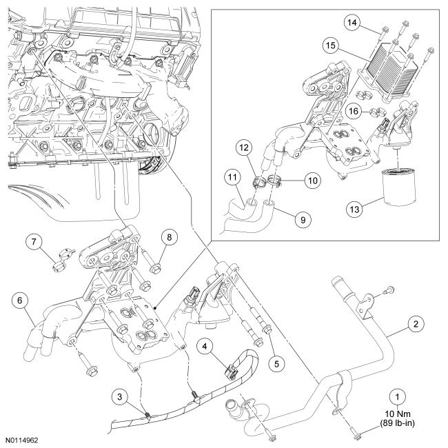
| Item | Part Number | Description |
|---|---|---|
| 1 | N605891 | Coolant tube assembly-to-oil filter adapter bolt (3 required) |
| 2 | 18663 | Coolant tube assembly |
| 3 | — | Wiring harness retainer (2 required) (part of 12B637) |
| 4 | — | Engine Oil Pressure (EOP) switch electrical connector (part of 12B637) |
| 5 | N807274 | Oil filter adapter bolt (2 required) |
| 6 | 6884 | Oil filter adapter |
| 7 | 6A636 | Oil filter adapter gasket |
| 8 | W500325 | Oil filter adapter bolt (6 required) |
| 9 | 6B850 | Coolant hose-to-oil filter adapter |
| 10 | 15161 | Coolant hose-to-oil filter adapter clamp |
| 11 | 6B851 | Lower radiator hose assembly-to-oil filter adapter |
| 12 | 15161 | Lower radiator hose assembly-to-oil filter adapter clamp |
| 13 | 6714 | Engine oil filter |
| 14 | N605893 | Oil cooler bolt (6 required) |
| 15 | 6A642 | Oil cooler |
| 16 | 6N818 | Oil cooler gasket (4 required) |
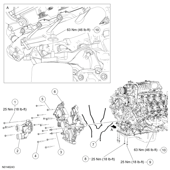
| Item | Part Number | Description |
|---|---|---|
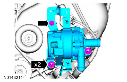
| 1 | N806177 | Coolant pump bolt (4 required) |
| 2 | 8501 | Coolant pump |
| 3 | N808586 | Engine front cover stud bolt (2 required) |
| 4 | N606063 | Engine front cover bolt (2 required) |
| 5 | N806177 | Engine front cover bolt (12 required) |
| 6 | 6C086 | Engine front cover |
| 7 | 6D081 | Engine front cover gasket |
| 8 | W701605 | Oil pan-to-engine front cover bolt |
| 9 | W701606 | Oil pan-to-engine front cover stud bolt (3 required) |
| 10 | W712530 | RH engine support insulator nut |
| 11 | W712530 | LH engine support insulator nut |
Removal
All vehicles
Vehicle equipped with the cooling package
All vehicles
NOTE: The heavy duty Engine Support Bar (303-F070) must be used with the draw screws from the light duty Engine Support Bar (303-F072). This will provide enough clearance between the SC and the Engine Support Bar, and enough clearance between the draw screw and the vehicle hood.
Install the Engine Support Bars.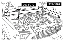
NOTICE: If metal or aluminum material is present in the oil cooler, mechanical concerns exist. Failure to correct these concerns may cause engine failure. To diagnose mechanical concerns, refer to Section 303-00 .
Remove the 6 bolts and the oil cooler or oil cooler thermostat.
NOTICE: Do not use metal scrapers, wire brushes, power abrasive discs or other abrasive means to clean the sealing surfaces. These tools cause scratches and gouges which make leak paths. Use a plastic scraping tool to remove all traces of old sealant.
Clean the mating surfaces with silicone gasket remover and metal surface prep. Follow the directions on the packaging.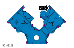
Installation
All vehicles
NOTE: The engine front cover must be installed and all fasteners final tightened within 4 minutes of applying the sealer. If this cannot be accomplished, install the engine front cover and tighten fasteners 6, 7, 8, 9, 10 and 11 to 8 Nm (71 lb-in) within 4 minutes of applying the sealer. All of the fasteners must then be final tightened within 1 hour of applying the sealer. If this time limit is exceeded, all sealant must be removed and the sealing area cleaned. To clean the sealing area, use silicone gasket remover and metal surface prep. Follow the directions on the packaging. Failure to follow this procedure can cause future oil leakage.
Apply a bead of Motorcraft® High Performance Engine RTV Silicone to the cylinder head-to-cylinder block joints and the oil pan-to-cylinder block joints as illustrated.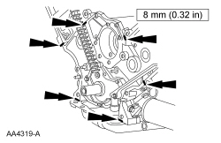
NOTE: Make sure that the engine front cover gaskets are in place on the engine front cover before installation.
Using new gaskets, position the engine front cover onto the dowels and install the 16 bolts. Tighten the bolts in the sequence shown in 2 stages.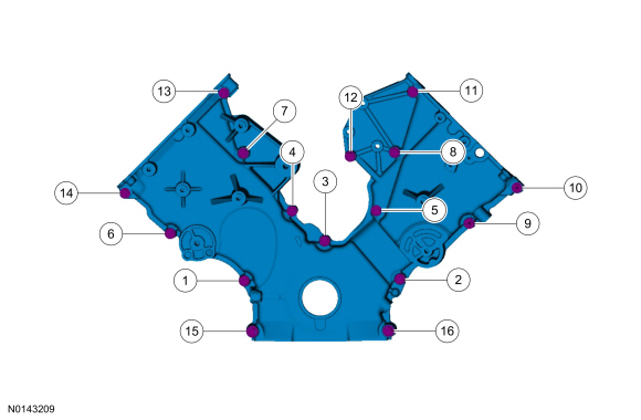
| Item | Part Number | Description |
|---|---|---|
| 1 | N806177 | Bolt, hex head pilot, M8 x 1.25 x 53 |
| 2 | N806177 | Bolt, hex head pilot, M8 x 1.25 x 53 |
| 3 | N806177 | Bolt, hex head pilot, M8 x 1.25 x 53 |
| 4 | N806177 | Bolt, hex head pilot, M8 x 1.25 x 53 |
| 5 | N806177 | Bolt, hex head pilot, M8 x 1.25 x 53 |
| 6 | N806177 | Bolt, hex head pilot, M8 x 1.25 x 53 |
| 7 | N806177 | Bolt, hex head pilot, M8 x 1.25 x 53 |
| 8 | N806177 | Bolt, hex head pilot, M8 x 1.25 x 53 |
| 9 | N808586 | Stud bolt, hex head pilot, M8 x 1.25 x 50 |
| 10 | N808586 | Stud bolt, hex head pilot, M8 x 1.25 x 50 |
| 11 | N806177 | Bolt, hex head pilot, M8 x 1.25 x 53 |
| 12 | N806177 | Bolt, hex head pilot, M8 x 1.25 x 53 |
| 13 | N806177 | Bolt, hex head pilot, M8 x 1.25 x 53 |
| 14 | N806177 | Bolt, hex head pilot, M8 x 1.25 x 53 |
| 15 | N606063 | Bolt, hex flange head pilot, M10 x 1.50 x 55 |
| 16 | N606063 | Bolt, hex flange head pilot, M10 x 1.50 x 55 |
NOTE: Clean and inspect the sealing surfaces with metal surface prep. Follow the directions on the packaging.
Using a new gasket, install the oil filter adapter and the 8 bolts. Tighten in the sequence shown in 2 stages.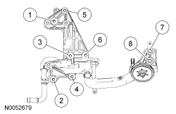
NOTE: Clean the sealing surfaces with metal surface prep. Follow the directions on the packaging. Inspect the mating surfaces.
NOTE: Oil cooler shown, oil cooler thermostat similar.
Using new gaskets, install the oil cooler or oil cooler thermostat and the 6 bolts. Tighten in the sequence shown in 2 stages.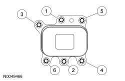
NOTICE: Do not tighten the engine support insulator nuts until the full weight of the engine is on the engine insulator or damage to the engine insulator may occur.
Install the LH and RH engine support insulator nuts.Vehicle equipped with the cooling package
All vehicles