303-452 (T93P-6565-AR)

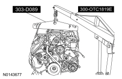
300-OTC1819E or equivalent

303-448 (T93P-6303-A)

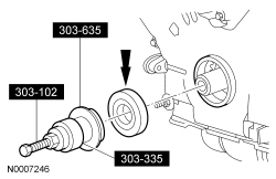
303-635

303-102 (T74P-6316-B)

303-335 (T88T-6701-A)

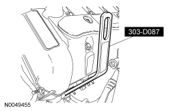
303-D087 (D93P-6001-A1) or equivalent

303-D089 (D93P-6001-A3) or equivalent

303-D055 (D85L-6000-A) or equivalent
SECTION 303-01C: Engine — 5.8L (4V)
| 2014 Mustang Workshop Manual
|
INSTALLATION
| Procedure revision date: 01/07/2013
|
| Compressor, Valve Spring
303-452 (T93P-6565-AR) |
| 2,200# Floor Crane, Fold Away
300-OTC1819E or equivalent |
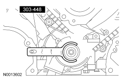
| Holding Tool, Crankshaft
303-448 (T93P-6303-A) |
| Installer, Crankshaft Front Oil Seal
303-635 |
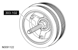
| Installer, Crankshaft Vibration Damper
303-102 (T74P-6316-B) |
| Installer, Front Cover Oil Seal
303-335 (T88T-6701-A) |
| Lifting Bracket, Engine (2 required)
303-D087 (D93P-6001-A1) or equivalent |
| Lifting Bracket, Engine
303-D089 (D93P-6001-A3) or equivalent |
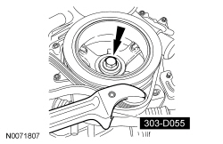
| Strap Wrench
303-D055 (D85L-6000-A) or equivalent |
| Item | Specification |
|---|---|
| Motorcraft® High Performance Engine RTV Silicone
TA-357 | WSE-M4G323-A6 |
| Motorcraft® Metal Surface Prep
ZC-31-A | — |
| Motorcraft® SAE 5W-50 Full Synthetic Motor Oil
XO-5W50-QGT | WSS-M2C931-B |
| Motorcraft® Silicone Brake Caliper Grease and Dielectric Compound
XG-3-A | ESE-M1C171-A |
| Motorcraft® Silicone Gasket Remover
ZC-30 | — |
Both cylinder heads
NOTICE: The gasket sealing surfaces on the cylinder head and the cylinder block must be clean. Failure to follow these instructions may result in engine damage. For additional information, refer to Cylinder Head in the Removal portion of this section.
NOTICE: The use of sealing aids (aviation cement, copper spray and glue) is not permitted. The gasket must be installed dry. Failure to follow these instructions may result in engine damage.
NOTICE: The new gasket has a film coating which is crucial to the ability of the gasket to seal correctly. Do not scratch the gasket.
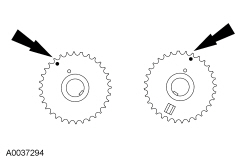
NOTE: RH head gasket shown, LH head gasket similar.
Install the head gasket over the dowel pins.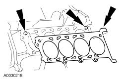
NOTICE: Cylinder head machining or milling is not authorized by the Ford Motor Company. Cylinder head flatness must be within 0.0254 mm (0.001 in) across a 38.1 mm (1.5 in) square area. Failure to follow these instructions may result in engine damage.
NOTICE: The gasket sealing surfaces on the cylinder head and the cylinder block must be clean. Do not use metal scrapers, wire brushes, power abrasive discs or other abrasive means to clean the sealing surfaces. These tools cause scratches and gouges which make leak paths. Use a plastic scraping tool to remove all traces of old sealant.
NOTICE: The use of sealing aids (aviation cement, copper spray and glue) is not permitted. The gasket must be installed dry. Failure to follow these instructions may result in engine damage.
NOTICE: Do not allow the dowels to scratch the sealing surface of the cylinder head during cylinder head installation. Failure to follow these instructions may result in engine damage.
NOTE: LH shown, RH similar.
Install the cylinder head on the dowels and the head gasket.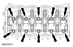
RH cylinder head

NOTE: Hand start the studs first.
Install 8 new RH exhaust manifold studs.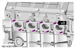
LH cylinder head
NOTE: Hand start the studs first.
Install 8 new LH exhaust manifold studs.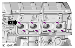

Both cylinder heads
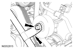
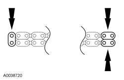
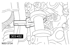
NOTICE: Do not compress the ratchet assembly. This will damage the ratchet assembly.
NOTE: LH shown, RH similar.
Compress each tensioner plunger, using an edge of a vise.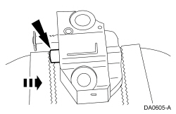
NOTICE: If the components are to be reinstalled, they must be installed in their original positions or damage to the engine may occur.
Install the hydraulic lash adjusters.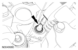
NOTICE: Only use hand tools when removing or installing the spark plugs, or damage may occur to the cylinder head or spark plugs.
NOTE: RH shown, LH similar.
Install the 8 spark plugs.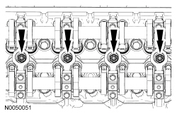
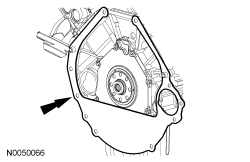
NOTE: If the engine front cover is not secured within 4 minutes, the sealant must be removed and the sealing area cleaned with metal surface prep. Allow to dry until there is no sign of wetness or 4 minutes, whichever is longer. Failure to follow this procedure can result in future oil leakage.
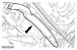
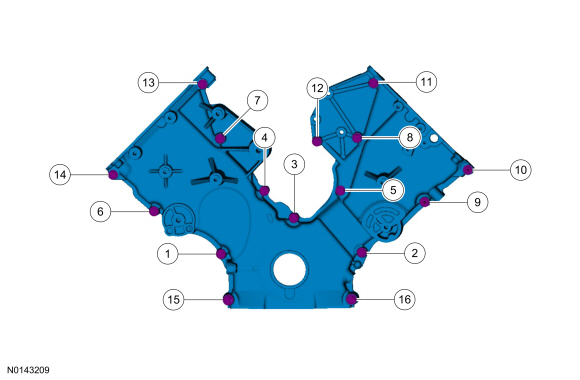
Apply Motorcraft® High Performance Engine RTV Silicone in the locations shown.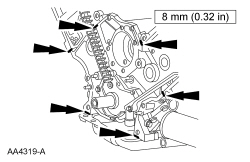
| Item | Part Number | Description |
|---|---|---|
| 1 | N806177 | Bolt, hex head pilot, M8 x 1.25 x 53 |
| 2 | N806177 | Bolt, hex head pilot, M8 x 1.25 x 53 |
| 3 | N806177 | Bolt, hex head pilot, M8 x 1.25 x 53 |
| 4 | N806177 | Bolt, hex head pilot, M8 x 1.25 x 53 |
| 5 | N806177 | Bolt, hex head pilot, M8 x 1.25 x 53 |
| 6 | N806177 | Bolt, hex head pilot, M8 x 1.25 x 53 |
| 7 | N806177 | Bolt, hex head pilot, M8 x 1.25 x 53 |
| 8 | N806177 | Bolt, hex head pilot, M8 x 1.25 x 53 |
| 9 | N808586 | Stud bolt, hex head pilot, M8 x 1.25 x 50 |
| 10 | N808586 | Stud bolt, hex head pilot, M8 x 1.25 x 50 |
| 11 | N806177 | Bolt, hex head pilot, M8 x 1.25 x 53 |
| 12 | N806177 | Bolt, hex head pilot, M8 x 1.25 x 53 |
| 13 | N806177 | Bolt, hex head pilot, M8 x 1.25 x 53 |
| 14 | N806177 | Bolt, hex head pilot, M8 x 1.25 x 53 |
| 15 | N606063 | Bolt, hex flange head pilot, M10 x 1.50 x 55 |
| 16 | N606063 | Bolt, hex flange head pilot, M10 x 1.50 x 55 |

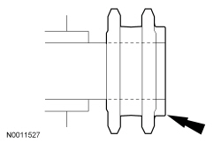
NOTE: If not secured within 4 minutes, the sealant must be removed and the sealing area cleaned. To clean the sealing area, use silicone gasket remover and metal surface prep. Follow the directions on the packaging. Failure to follow this procedure can cause future oil leakage.
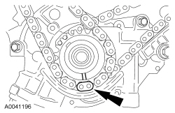
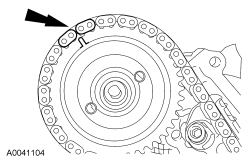
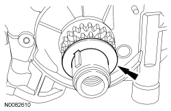
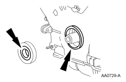
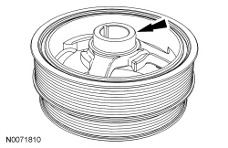
Apply Motorcraft® High Performance Engine RTV Silicone to the Woodruff key slot on the crankshaft pulley.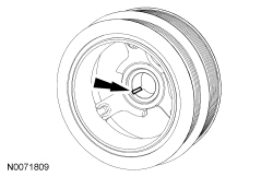
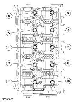
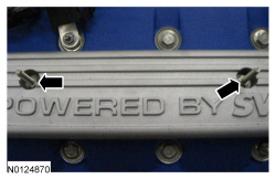
NOTE: If the valve covers are not secured within 4 minutes, the sealant must be removed and the sealing area cleaned with metal surface prep. Allow to dry until there is no sign of wetness or 4 minutes, whichever is longer. Failure to follow this procedure can cause future oil leakage.
NOTE: LH shown, RH similar.
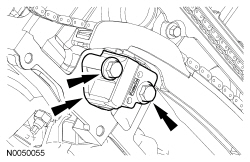
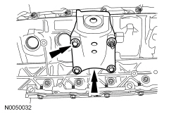
Apply Motorcraft® High Performance Engine RTV Silicone in the locations shown.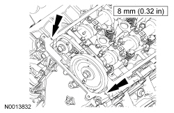
NOTE: If the valve covers are not secured within 4 minutes, the sealant must be removed and the sealing area cleaned with metal surface prep. Allow to dry until there is no sign of wetness or 4 minutes, whichever is longer. Failure to follow this procedure can cause future oil leakage.
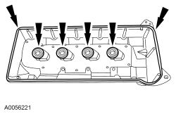
Install the RH valve cover and the 10 bolts. Tighten in the sequence shown.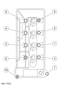
NOTE: If the valve covers are not secured within 4 minutes, the sealant must be removed and the sealing area cleaned with metal surface prep. Allow to dry until there is no sign of wetness or 4 minutes, whichever is longer. Failure to follow this procedure can cause future oil leakage.
Install the LH valve cover and the 10 bolts. Tighten in the sequence shown.
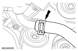
NOTE: LH shown, RH similar.
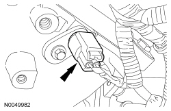
If equipped, install the LH and RH block drain plugs.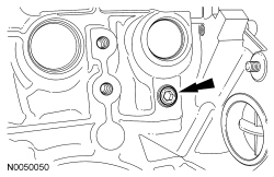
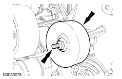
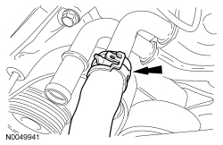
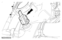
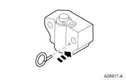
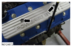
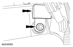
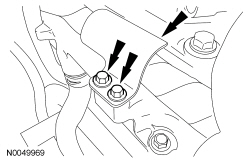
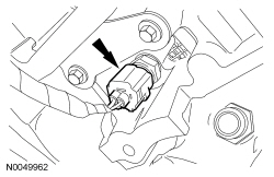
NOTE: Lubricate the new oil level indicator tube O-ring seal with clean engine oil prior to installation.
Using a new O-ring seal, install the oil level indicator tube, bolt and oil level indicator.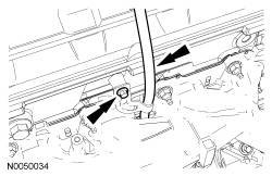
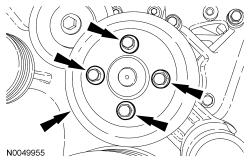
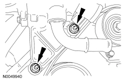
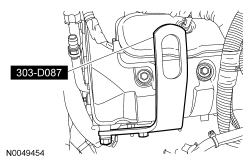
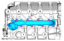
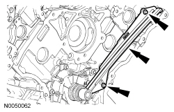
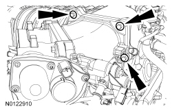
NOTE: Clean and inspect the sealing surfaces with metal surface prep. Follow the directions on the packaging.
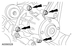
Using a new gasket, install the oil filter adapter and the 8 bolts. Tighten in the sequence shown in 2 stages.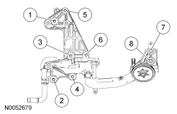
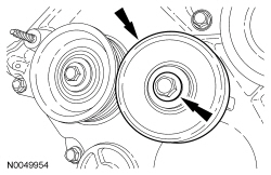
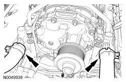
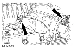
NOTE: Clean and inspect the sealing surfaces with metal surface prep. Follow the directions on the packaging.
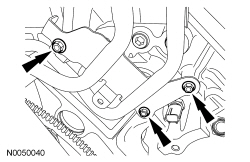
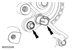
NOTE: Oil cooler shown, oil cooler thermostat similar.
Using a new gasket, install the oil cooler and the 6 bolts. Tighten in the sequence shown in 2 stages.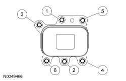
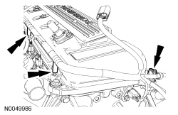
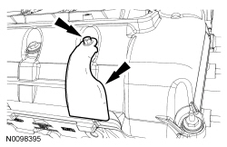
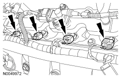
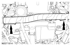
NOTICE: If the engine is repaired or replaced because of upper engine failure, typically including valve or piston damage, check the intake manifold for metal debris. If metal debris is found, install a new intake manifold. Failure to follow these instructions can result in engine damage.
NOTE: Clean and inspect the sealing surfaces with metal surface prep. Follow the directions on the packaging.
Using new intake manifold gaskets, install the intake manifold and the 14 bolts. Tighten in the sequence shown.
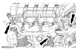
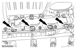
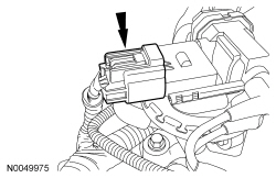
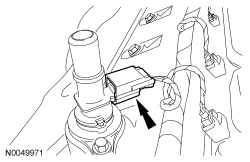
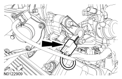
NOTE: Apply a light film of brake dielectric grease to the inside of the coil boots before installation.
Install the 4 LH coil-on-plugs.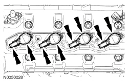
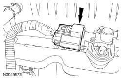
NOTE: Apply a light film of brake dielectric grease to the inside of the coil boots before installation.
Install the 4 RH coil-on-plugs.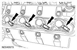

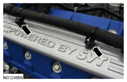
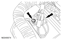
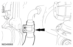
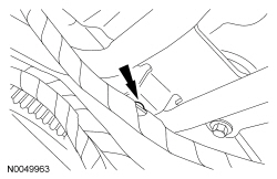
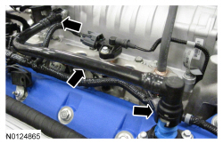
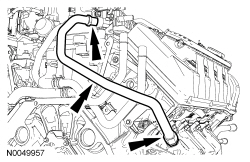
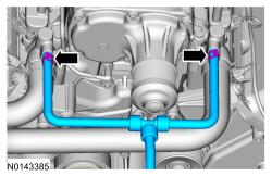
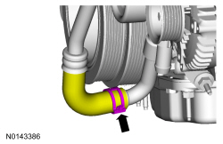
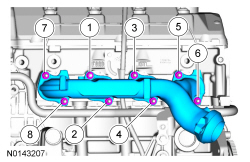
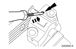
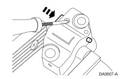
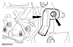
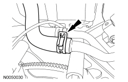
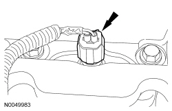
NOTE: Hand start the top fitting first.
Install the EGR tube.