
NUD105-R025D or equivalent

FLU77-4 or equivalent
SECTION 303-06: Starting System
| 2014 Mustang Workshop Manual
|
DIAGNOSIS AND TESTING
| Procedure revision date: 01/07/2013
|
| Flex Probe Kit
NUD105-R025D or equivalent |
| Fluke 77-IV Digital Multimeter
FLU77-4 or equivalent |
Principles of Operation
The starting system is electronically controlled by the PCM. The PCM receives the following inputs:
When the ignition switch is placed in the START position, a starter motor request signal is also sent to the PCM. If the PCM recognizes the correct input signals, it provides the starter relay coil with both voltage and ground. The starter relay contacts close, providing voltage to the starter solenoid, allowing the starter motor to activate.
Vehicles equipped with an automatic transmission have a digital TR sensor. The TR sensor prevents operation of the starter motor unless the transmission is in NEUTRAL or PARK.
Vehicles equipped a manual transmission have a CPP switch. The CPP switch prevents operation of the starter motor unless the clutch pedal is fully pressed.
Inspection and Verification
 WARNING: Always disconnect the battery ground cable at the battery before disconnecting the starter motor battery terminal lead. If a tool is shorted at the starter motor battery terminal, the tool can quickly heat enough to cause a skin burn. Failure to follow this instruction may result in serious personal injury.
NOTE: The anti-theft system must be functioning correctly before a logical starting system diagnosis can be carried out. Address anti-theft system concerns before continuing. Refer to Section 419-01B .
Visual Inspection Chart
| Mechanical | Electrical |
|---|---|
|
|
NOTE: Make sure to use the latest scan tool software release.
If the cause is not visually evident, connect the scan tool to the Data Link Connector (DLC).NOTE: The Vehicle Communication Module (VCM) LED prove out confirms power and ground from the DLC are provided to the VCM .
If the scan tool does not communicate with the VCM :DTC Chart
PCM DTC Chart
| DTC | Description | Action |
|---|---|---|
| P0512 | Starter Request Circuit | GO to Pinpoint Test A . |
| P0705 | Transmission Range (TR) Sensor A Circuit (PRNDL Input) | Refer to the appropriate section in Group 307 for the procedure. |
| P0708 | TR Sensor A Circuit High | Refer to the appropriate section in Group 307 for the procedure. |
| P0830 | Clutch Pedal Switch A Circuit | GO to Pinpoint Test A . |
| P1260 | Theft Detected, Vehicle Immobilized | REFER to the DTC Chart in Section 419-01B . All other PCM DTCs, REFER to Section 303-14 . |
| P1702 | TR Sensor Circuit Intermittent | Refer to the appropriate section in Group 307 for the procedure. |
| P1704 | TR circuit is not indicating PARK/NEUTRAL during self-test | Refer to the appropriate section in Group 307 for the procedure. |
| P1705 | TR circuit is not indicating PARK/NEUTRAL during self-test | Refer to the appropriate section in Group 307 for the procedure. |
| P1921 | TR Signal | Refer to the appropriate section in Group 307 for the procedure. |
Symptom Chart
| Condition | Possible Sources | Action |
|---|---|---|
|
| |
|
| |
|
|
|
|
|
|
|
|
Pinpoint Tests
Pinpoint Test A: The Engine Does Not Crank
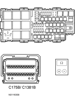
Refer to Wiring Diagrams Cell 20 , Starting System for schematic and connector information.
NOTICE: Use the correct probe adapter(s) when making measurements. Failure to use the correct probe adapter(s) may damage the connector.
When the ignition switch is turned to the START position, the PCM receives a starter motor request signal. Voltage is supplied to the starter relay from the PCM. The PCM receives a signal from the digital Transmission Range (TR) sensor that the vehicle is in PARK or NEUTRAL (vehicles equipped with an automatic transmission) or from the Clutch Pedal Position (CPP) switch when the clutch pedal is fully depressed (vehicles equipped with manual transmission). A ground is supplied from the PCM causing the starter relay coil to energize and the relay contacts to close. This allows voltage to be supplied from Battery Junction Box (BJB) fuse 19 (30A) to the relay contacts, which then flows to the starter solenoid. The solenoid is grounded at the starter motor. Energizing the starter solenoid engages the starter drive into the ring gear and closes the solenoid contacts allowing voltage directly from the battery to the starter motor to start the engine. The PCM will disengage the starter motor based on engine running (rpm threshold), a set crank time has been exceeded or the ignition switch has been turned to the OFF position.
| Test Step | Result / Action to Take | |||||||||
|---|---|---|---|---|---|---|---|---|---|---|
| A1 CHECK THE BATTERY | ||||||||||
| Yes
GO to A2 . No CHARGE or INSTALL a new battery. REFER to Section 414-01 . TEST the system for normal operation. | |||||||||
| A2 CHECK THE PCM FOR DTCs | ||||||||||
| Yes
If DTC P0512 is retrieved, GO to A14 . If PCM DTC P1260 is retrieved, REFER to Section 419-01B . All other PCM DTCs, REFER to Section 303-14 . No For automatic transmissions,GO to A3 . For manual transmissions,GO to A4 . | |||||||||
| A3 CHECK THE PCM TR SENSOR PID | ||||||||||
| Yes
GO to A5 . No REFER to Section 307-01 , to diagnose the TR sensor. | |||||||||
| A4 CHECK THE PCM CLUTCH PEDAL AT OR NEAR BOTTOM OF TRAVEL (CPP_ BOT) PID | ||||||||||
| Yes
GO to A5 . No GO to A18 . | |||||||||
| A5 CHECK THE PCM STARTER MOTOR RELAY ENABLE (STRT_RLY) PID | ||||||||||
| Yes
GO to A6 . No GO to A16 . | |||||||||
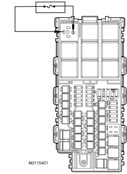
| A6 CHECK THE STARTER MOTOR RELAY | ||||||||||
| Yes
INSTALL a new starter relay. TEST the system for normal operation. No GO to A7 . | |||||||||
| A7 CHECK THE VOLTAGE TO THE STARTER MOTOR RELAY | ||||||||||
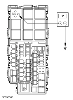 | Yes
GO to A8 . No VERIFY BJB fuse 19 (30A) is OK. If OK, REPAIR circuit SBB19 (BU/RD) for an open. TEST the system for normal operation. If not OK, REFER to the Wiring Diagrams manual to identify the possible causes of the circuit short. | |||||||||
| A8 CHECK THE STARTER MOTOR | ||||||||||
 | Yes
GO to A14 . No GO to A9 . | |||||||||
| A9 CHECK THE BATTERY GROUND CABLE | ||||||||||
 | Yes
GO to A10 . No INSTALL a new battery ground cable. REFER to Section 414-01 . TEST the system for normal operation. | |||||||||
| A10 CHECK THE STARTER MOTOR GROUND | ||||||||||
 | Yes
GO to A11 . No CLEAN the starter motor mounting flange and make sure the starter motor is correctly mounted. TEST the system for normal operation. | |||||||||
| A11 CHECK THE VOLTAGE TO THE STARTER MOTOR | ||||||||||
 | Yes
GO to A12 . No INSTALL a new positive battery cable. REFER to Section 414-01 . TEST the system for normal operation. | |||||||||
| A12 CHECK THE STARTER MOTOR | ||||||||||
 | Yes
GO to A13 . No INSTALL a new starter motor. REFER to Starter Motor — 3.7L or Starter Motor — 5.0L (4V) or Starter Motor — 5.8L (4V) . TEST the system for normal operation. | |||||||||
| A13 CHECK FOR START INPUT AT THE STARTER | ||||||||||
 | Yes
CLEAN the starter motor solenoid S-terminal and connector. CHECK the wiring and the starter motor for a loose or intermittent connection. TEST the system for normal operation. No REPAIR circuit CDC25 (BN/GN) for an open. TEST the system for normal operation. | |||||||||
| A14 CHECK THE PCM START CIRCUITS FOR A SHORT TO GROUND | ||||||||||
 | Yes
GO to A15 . No REPAIR the affected circuit for a short to ground. TEST the system for normal operation. | |||||||||
| A15 CHECK THE PCM START CIRCUITS FOR AN OPEN | ||||||||||
 | Yes
INSTALL a new PCM. REFER to Section 303-14 . TEST the system for normal operation. No REPAIR the affected circuit for an open. TEST the system for normal operation. | |||||||||
| A16 CHECK THE START CIRCUIT FOR VOLTAGE AT THE PCM | ||||||||||
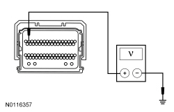 | Yes
INSTALL a new PCM. REFER to Section 303-14 . TEST the system for normal operation. No GO to A17 . | |||||||||
| A17 CHECK THE IGNITION SWITCH | ||||||||||
| Yes
REPAIR circuit CDC35 (BU/WH) for an open. TEST the system for normal operation. No INSTALL a new ignition switch. REFER to Section 211-05 . TEST the system for normal operation. | |||||||||
| A18 CHECK THE BOTTOM OF TRAVEL CIRCUIT FOR AN OPEN | ||||||||||
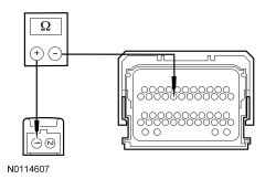  | Yes
GO to A19 . No REPAIR circuit CE903 (BU/OG) for an open. TEST the system for normal operation. | |||||||||
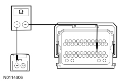
| A19 CHECK THE CPP GROUND CIRCUIT FOR AN OPEN | ||||||||||
 | Yes
GO to A20 . No REPAIR circuit GD129 (BK/YE) for an open. TEST the system for normal operation. | |||||||||
| A20 CHECK THE CPP SWITCH | ||||||||||
  | Yes
INSTALL a new PCM. REFER to Section 303-14 . TEST the system for normal operation. No INSTALL a new CPP switch. REFER to Section 303-14 . TEST the system for normal operation. |
Pinpoint Test B: Unusual Starter Noise
Refer to Wiring Diagrams Cell 20 , Starting System for schematic and connector information.
Correct starter operation relies on correct mounting of the starter to the engine, alignment of the starter ring gear to the flywheel or flexplate and correct functioning of the starter assembly (internal gears, bearings).
| Test Step | Result / Action to Take |
|---|---|
| B1 CHECK THE STARTER MOTOR MOUNTING | |
| Yes
GO to B2 . No INSTALL the starter motor correctly. REFER to Starter Motor — 3.7L or Starter Motor — 5.0L (4V) or Starter Motor — 5.8L (4V) . TEST the system for normal operation. |
| B2 CHECK FOR ENGINE NOISE | |
 | Yes
GO to B3 . No REFER to Section 303-00 to continue the diagnosis. |
| B3 CHECK FOR UNUSUAL WEAR | |
| Yes
INSTALL a new flexplate/flywheel ring gear. EXAMINE the starter pinion teeth. If damaged, INSTALL a new starter motor. TEST the system for normal operation. No INSTALL a new starter motor. REFER to Starter Motor — 3.7L or Starter Motor — 5.0L (4V) or Starter Motor — 5.8L (4V) . TEST the system for normal operation. |
Component Tests
WARNING: Always disconnect the battery ground cable at the battery before disconnecting the starter motor battery terminal lead. If a tool is shorted at the starter motor battery terminal, the tool can quickly heat enough to cause a skin burn. Failure to follow this instruction may result in serious personal injury.
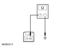
Always make the Fluke 77-IV Digital Multimeter connections at the component terminal rather than at the wiring end connector. Making a connection at the wiring end connector could result in false readings because the meter will not pick up a high resistance between the wiring connector and the component.
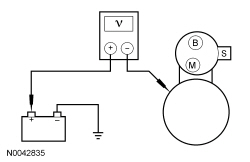
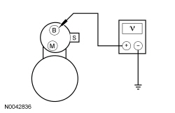
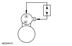
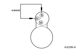
Starter Motor — Motor Feed Circuit
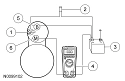
| Item | Part Number | Description |
|---|---|---|
| 1 | — | S-terminal |
| 2 | — | Remote starter switch |
| 3 | 10655 | Battery |
| 4 | — | Fluke 77-IV Digital Multimeter |
| 5 | — | B-terminal |
| 6 | — | M-terminal |
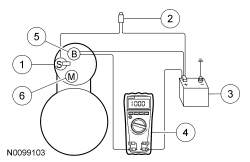
| Item | Part Number | Description |
|---|---|---|
| 1 | — | S-terminal |
| 2 | — | Remote starter switch |
| 3 | 10655 | Battery |
| 4 | — | Fluke 77-IV Digital Multimeter |
| 5 | — | B-terminal |
| 6 | — | M-terminal |
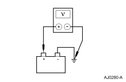
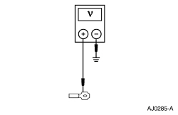
Starter Motor — Ground Circuit
A slow cranking condition can be caused by resistance in the ground or return portion of the cranking circuit. Check the voltage drop in the ground circuit as follows: