
303-476 (T94P-9472-A)

SECTION 303-14: Electronic Engine Controls
| 2014 Mustang Workshop Manual
|
REMOVAL AND INSTALLATION
| Procedure revision date: 01/07/2013
|
| Socket, Exhaust Gas Oxygen Sensor
303-476 (T94P-9472-A) |
| Vehicle Communication Module (VCM) and Integrated Diagnostic System (IDS) software with appropriate hardware, or equivalent scan tool
|
| Item | Specification |
|---|---|
| High Temperature Nickel Anti-Seize Lubricant
XL-2 | — |
| Motorcraft® SAE 5W-20 Premium Synthetic Blend Motor Oil (US); Motorcraft® SAE 5W-20 Super Premium Motor Oil (Canada)
XO-5W20-QSP (US); CXO-5W20-LSP12 (Canada) | WSS-M2C945-A |
| Penetrating and Lock Lubricant (US); Penetrating Fluid (Canada)
XL-1 (US); CXC-51-A (Canada) | — |
NOTE: The battery tray must be removed to access the RH exhaust or intake CMP . For additional information, refer to Section 414-01 .
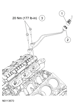
NOTE: Lubricate the Camshaft Position (CMP) sensor O-ring seal with clean engine oil. LH shown, RH similar.
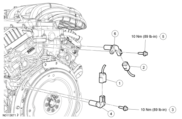
| Item | Part Number | Description |
|---|---|---|
| 1 | — | LH exhaust Camshaft Position (CMP) sensor electrical connector (part of 12A581) |
| 2 | — | LH intake CMP sensor electrical connector (part of 12A581) |
| 3 | W503275 | LH exhaust CMP sensor bolt |
| 4 | 6B288 | LH exhaust CMP sensor |
| 5 | W503275 | LH intake CMP sensor bolt |
| 6 | 6B288 | LH intake CMP sensor |
NOTE: After installing the Crankshaft Position (CKP) sensor, use the scan tool to perform the Misfire Monitor Neutral Profile Correction procedure, following the on-screen instructions.
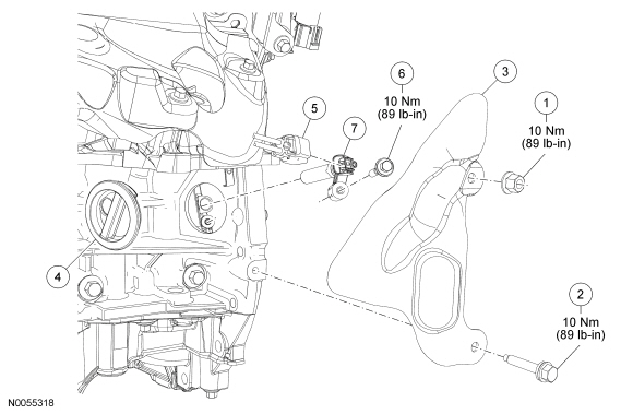
| Item | Part Number | Description |
|---|---|---|
| 1 | W520101 | Heat shield nut |
| 2 | W701669 | Heat shield bolt |
| 3 | 6K342 | Heat shield |
| 4 | 6C070 | Rubber grommet cover |
| 5 | — | Crankshaft Position (CKP) sensor electrical connector (part of 12A581) |
| 6 | W712315 | CKP sensor bolt (part of 6C315) |
| 7 | 6C315 | CKP sensor |
NOTE: The lower intake manifold must be removed to access the CHT sensor. For additional information, refer to Section 303-01A .
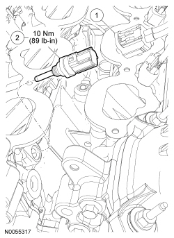
| Item | Part Number | Description |
|---|---|---|
| 1 | — | Cylinder Head Temperature (CHT) sensor electrical connector (part of 12A581) |
| 2 | 6G004 | CHT sensor |
NOTE: For Heated Oxygen Sensor (HO2S) removal and installation, refer to Heated Oxygen Sensor (HO2S) in this section.
NOTE: If necessary, lubricate the Catalyst Monitor Sensor (CMS) with penetrating and lock lubricant to assist in removal.
NOTE: Apply anti-seize to the threads of the CMS prior to installing.
NOTE: The correct torque wrench setting must be calculated when using the Exhaust Gas Oxygen Sensor Socket to install the CMS . Refer to the Torque Wrench Adapter Formulas in the Appendix.
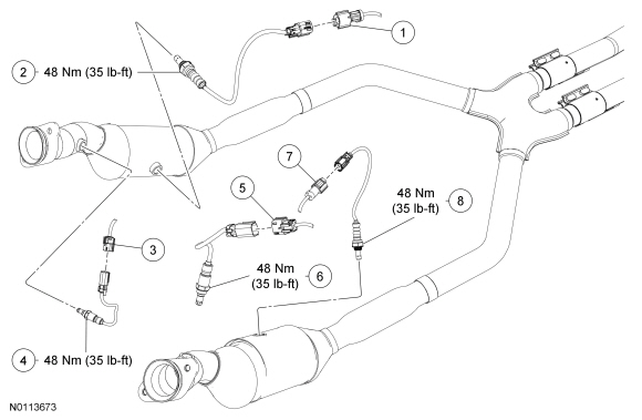
| Item | Part Number | Description |
|---|---|---|
| 1 | — | RH Catalyst Monitor Sensor (CMS) electrical connector |
| 2 | 9F472 | RH CMS |
| 3 | — | RH Heated Oxygen Sensor (HO2S) electrical connector |
| 4 | 9G444 | RH HO2S |
| 5 | — | LH HO2S electrical connector |
| 6 | 9G444 | LH HO2S |
| 7 | — | LH CMS electrical connector |
| 8 | 9F472 | LH CMS |
NOTE: The lower intake manifold must be removed to access the KS . For additional information, refer to Section 303-01A .
NOTE: LH cylinder head removed in graphic for clarity.
| Item | Part Number | Description |
|---|---|---|
| 1 | — | Knock Sensor (KS) electrical connector (part of 12A581) |
| 2 | 12A699 | KS |
| 3 | W704749 | KS bolt (2 required) |
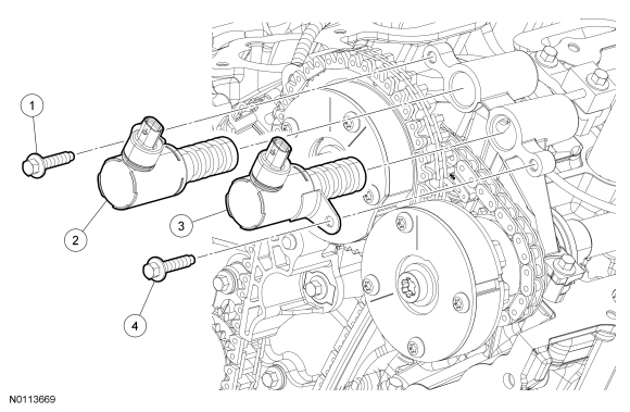
NOTE: The valve cover must be removed to access the VCT oil control solenoid. For additional information, refer to Section 303-01A .
NOTE: LH shown, RH similar.
NOTE: To install, tighten bolt(s) to 8 Nm (71 lb-in) plus an additional 20 degrees.
| Item | Part Number | Description |
|---|---|---|
| 1 | W500215 | LH intake Variable Camshaft Timing (VCT) oil control solenoid bolt |
| 2 | 6B297 | LH intake VCT oil control solenoid |
| 3 | 6B297 | LH exhaust VCT oil control solenoid |
| 4 | W500215 | LH exhaust VCT oil control solenoid bolt |