
303-476 (T94P-9472-A)

SECTION 303-14: Electronic Engine Controls
| 2014 Mustang Workshop Manual
|
REMOVAL AND INSTALLATION
| Procedure revision date: 01/07/2013
|
| Socket, Exhaust Gas Oxygen Sensor
303-476 (T94P-9472-A) |
| Vehicle Communication Module (VCM) and Integrated Diagnostic System (IDS) software with appropriate hardware, or equivalent scan tool
|
| Item | Specification |
|---|---|
| High Temperature Nickel Anti-Seize Lubricant
XL-2 | — |
| Penetrating and Lock Lubricant (US); Penetrating Fluid (Canada)
XL-1 (US); CXC-51-A (Canada) | — |
NOTE: RH shown, LH similar.
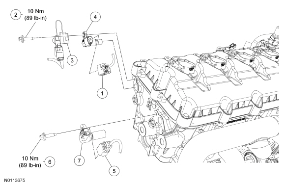
| Item | Part Number | Description |
|---|---|---|
| 1 | — | RH intake Camshaft Position (CMP) sensor electrical connector (part of 12A581) |
| 2 | W503277 | RH intake CMP sensor bolt |
| 3 | 18801 | Radio ignition interference capacitor |
| 4 | 6B288 | RH intake CMP sensor |
| 5 | — | RH exhaust CMP sensor electrical connector (part of 12A581) |
| 6 | W503277 | RH exhaust CMP sensor bolt |
| 7 | 6B288 | RH exhaust CMP sensor |
NOTE: After installing the Crankshaft Position (CKP) sensor, use the scan tool to perform the Misfire Monitor Neutral Profile Correction procedure, following the on-screen instructions.
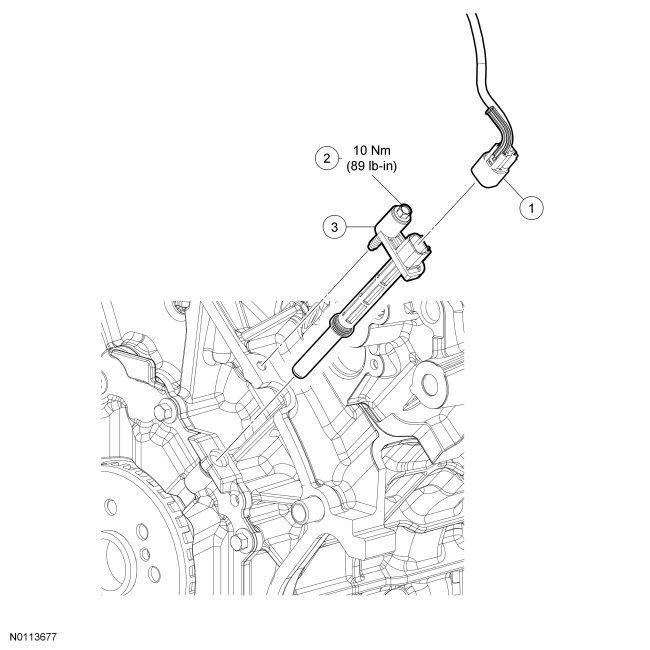
| Item | Part Number | Description |
|---|---|---|
| 1 | — | Crankshaft Position (CKP) sensor electrical connector (part of 12A581) |
| 2 | — | CKP sensor bolt (part of 6C315) |
| 3 | 6C315 | CKP sensor |
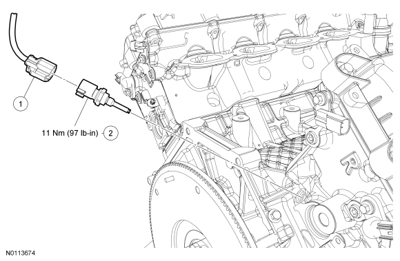
| Item | Part Number | Description |
|---|---|---|
| 1 | — | Cylinder Head Temperature (CHT) sensor electrical connector (part of 12A581) |
| 2 | 6G004 | CHT sensor |
NOTE: For Heated Oxygen Sensor (HO2S) removal and installation, refer to Heated Oxygen Sensor (HO2S) in this section.
NOTE: If necessary, lubricate the Catalyst Monitor Sensor (CMS) with penetrating and lock lubricant to assist in removal.
NOTE: Apply anti-seize to the threads of the CMS prior to installing.
NOTE: The correct torque wrench setting must be calculated when using the Exhaust Gas Oxygen Sensor Socket to install the CMS . Refer to the Torque Wrench Adapter Formulas in the Appendix.
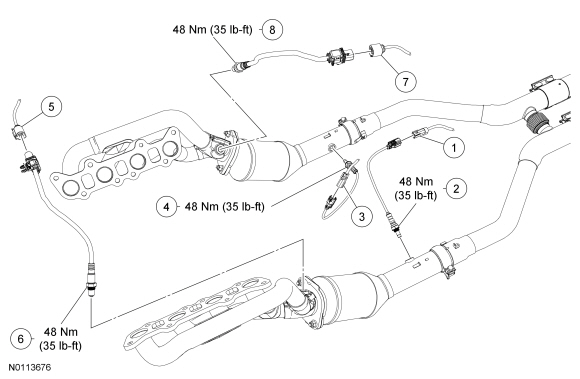
| Item | Part Number | Description |
|---|---|---|
| 1 | — | LH Catalyst Monitor Sensor (CMS) electrical connector |
| 2 | 9F472 | LH CMS |
| 3 | — | RH CMS electrical connector |
| 4 | 9F472 | RH CMS |
| 5 | — | LH Heated Oxygen Sensor (HO2S) electrical connector |
| 6 | 9G444 | LH HO2S |
| 7 | — | RH HO2S electrical connector |
| 8 | 9G444 | RH HO2S |
NOTE: The intake manifold must be removed to access the KS . For additional information, refer to Section 303-01B .
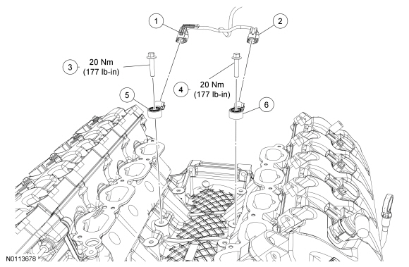
| Item | Part Number | Description |
|---|---|---|
| 1 | — | RH Knock Sensor (KS) electrical connector (part of 14B485) |
| 2 | — | LH KS electrical connector (part of 14B485) |
| 3 | W500110 | RH KS bolt |
| 4 | W500110 | LH KS bolt |
| 5 | 12A699 | RH KS |
| 6 | 12A699 | LH KS |
NOTICE: The Variable Camshaft Timing (VCT) variable force solenoid pins must be fully depressed to avoid interference with the VCT valve tips during installation. Failure to follow these instructions can result in damage to the engine.
NOTE: LH shown, RH similar.
NOTE: It is necessary to remove the valve cover to perform this procedure. For additional information, refer to Section 303-01B .
NOTE: To install, tighten bolts to 8 Nm (71 lb-in) plus an additional 30 degrees.
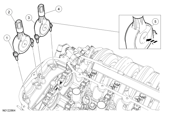
| Item | Part Number | Description |
|---|---|---|
| 1 | W700005 | LH exhaustVariable Camshaft Timing (VCT) variable force solenoid bolt (part of 6M280) (2 required) |
| 2 | 6M280 | LH exhaust VCT variable force solenoid |
| 3 | W700005 | LH intake VCT variable force solenoid bolt (part of 6M280) (2 required) |
| 4 | 6M280 | LH intake VCT variable force solenoid |
| 5 | — | VCT variable force solenoid pin (part of 6M280) (depress prior to installing solenoid) |