
303-476 (T94P-9472-A)

SECTION 303-14: Electronic Engine Controls
| 2014 Mustang Workshop Manual
|
REMOVAL AND INSTALLATION
| Procedure revision date: 01/07/2013
|
| Socket, Exhaust Gas Oxygen Sensor
303-476 (T94P-9472-A) |
| Vehicle Communication Module (VCM) and Integrated Diagnostic System (IDS) software with appropriate hardware, or equivalent scan tool
|
| Item | Specification |
|---|---|
| High Temperature Nickel Anti-Seize Lubricant
XL-2 | — |
| Motorcraft® SAE 5W-50 Full Synthetic Motor Oil
XO-5W50-QGT or equivalent | WSS-M2C931-B |
| Penetrating and Lock Lubricant (US); Penetrating Fluid (Canada)
XL-1 (US); CXC-51-A (Canada) | — |
| Item | Part Number | Description |
|---|---|---|
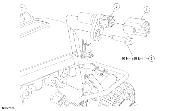
| 1 | — | CMP sensor electrical connector |
| 2 | N806155 | CMP sensor bolt |
| 3 | 6B288 | CMP sensor |
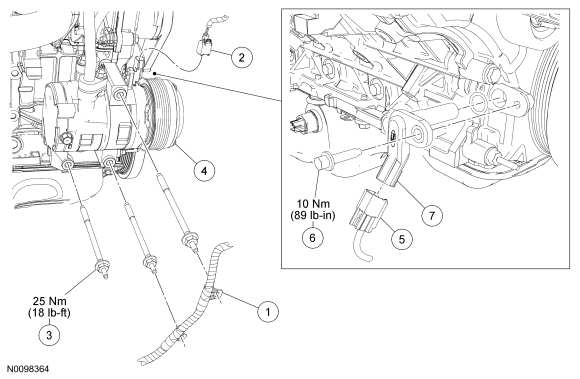
NOTE: The SC belt must be removed to perform this procedure. For additional information, refer to Section 303-05 .
NOTE: The A/C compressor must be positioned aside to access the CKP sensor, it is not necessary to remove the A/C compressor from the vehicle.
NOTE: After installing the CKP sensor, use the scan tool to perform the Misfire Monitor Neutral Profile Correction procedure, following the on-screen instructions.
| Item | Part Number | Description |
|---|---|---|
| 1 | — | Wiring harness retainer (part of 12B637) |
| 2 | — | A/C compressor electrical connector |
| 3 | W707821 | A/C compressor stud bolt (3 required) |
| 4 | 190629 | A/C compressor |
| 5 | — | Crankshaft Position (CKP) sensor electrical connector |
| 6 | N806155 | CKP sensor bolt |
| 7 | 6C315 | CKP sensor |
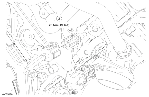
NOTE: The battery tray must be removed to perform this procedure. Refer to Section 414-01 .
NOTE: Do not reuse the CHT sensor, install a new sensor.
| Item | Part Number | Description |
|---|---|---|
| 1 | — | CHT sensor electrical connector |
| 2 | 6G004 | CHT sensor |
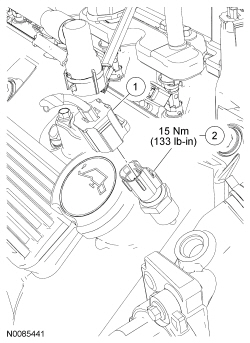
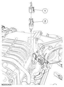
NOTE: Drain the cooling system prior to removing the ECT sensor. Refer to Section 303-03A .
NOTE: Fill and bleed the cooling system after installing the ECT sensor. Refer to Section 303-03A .
| Item | Part Number | Description |
|---|---|---|
| 1 | — | ECT sensor electrical connector |
| 2 | 12A648 | ECT sensor |
 WARNING: Do not smoke, carry lighted tobacco or have an open flame of any type when working on or near any fuel-related component. Highly flammable mixtures are always present and may be ignited. Failure to follow these instructions may result in serious personal injury.
WARNING: Before working on or disconnecting any of the fuel tubes or fuel system components, relieve the fuel system pressure to prevent accidental spraying of fuel. Fuel in the fuel system remains under high pressure, even when the engine is not running. Failure to follow this instruction may result in serious personal injury.
NOTE: Release the fuel system pressure prior to removing the fuel rail pressure and temperature sensor. Refer to Section 310-00 .
NOTE: Inspect the O-ring seal and install new as necessary. Lubricate the O-ring seal with clean engine oil.
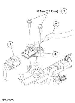
| Item | Part Number | Description |
|---|---|---|
| 1 | — | Fuel rail pressure and temperature sensor electrical connector |
| 2 | 9C482/9E498 | Vacuum hose |
| 3 | W705870 | Fuel rail pressure and temperature sensor bolts (2 required) |
| 4 | 9G756 | Fuel rail pressure and temperature sensor |
| 5 | — | O-ring seal |
NOTE: For HO2S removal and installation, refer to Heated Oxygen Sensor (HO2S) in this section.
NOTE: If necessary, lubricate the CMS with penetrating and lock lubricant to assist in removal.
NOTE: Apply anti-seize to the threads of the CMS prior to installing.
NOTE: The correct torque wrench setting must be calculated when using the Exhaust Gas Oxygen Sensor Socket to install the CMS . Refer to the Torque Wrench Adapter Formulas in the Appendix.
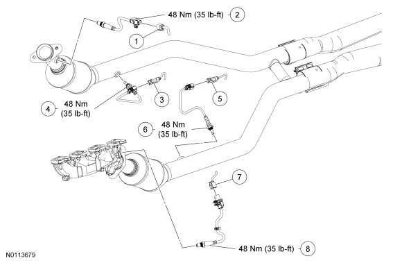
| Item | Part Number | Description |
|---|---|---|
| 1 | — | RH HO2S electrical connector |
| 2 | 9G444 | RH HO2S |
| 3 | — | RH CMS electrical connector |
| 4 | 9F472 | RH CMS |
| 5 | — | LH CMS electrical connector |
| 6 | 9F472 | LH CMS |
| 7 | — | LH HO2S electrical connector |
| 8 | 9G444 | LH HO2S |
NOTE: Tighten the IAT2 sensor in 2 stages. During stage 2, do not tighten the IAT2 sensor more than one full turn and do not rotate the IAT2 sensor counterclockwise after tightening.
| Item | Part Number | Description |
|---|---|---|
| 1 | — | IAT2 sensor electrical connector |
| 2 | 12A697 | IAT2 sensor |
NOTICE: Note the position and orientation of each KS . The sensors must be installed in the same position as removed or damage to the sensors may occur.
NOTE: The intake manifold must be removed to perform this procedure. Refer to Section 303-01C .
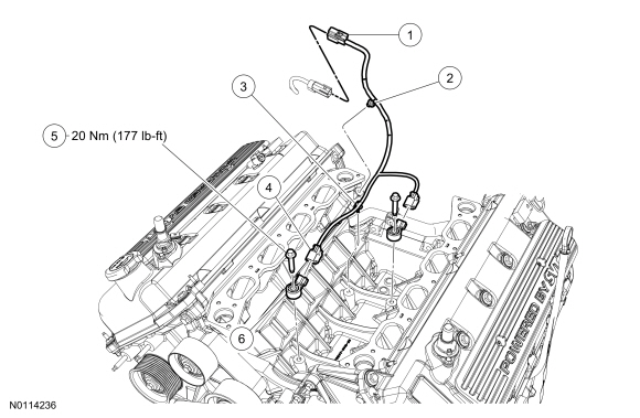
| Item | Part Number | Description |
|---|---|---|
| 1 | — | KS harness electrical connector (part of 14B485) |
| 2 | — | Pin-type retainer (part of 14B485) |
| 3 | — | Pin-type retainer (part of 14B485) |
| 4 | — | KS electrical connector (part of 14B485) (2 required) |
| 5 | W500225 | KS bolt (2 required) |
| 6 | 12A699 | KS (2 required) |