
204-354

GSP9700 Series
SECTION 204-04: Wheels and Tires
| 2014 Mustang Workshop Manual
|
DIAGNOSIS AND TESTING
| Procedure revision date: 01/07/2013
|
| Digital Tire Gauge
204-354 |
| Hunter Road Force® Wheel Balancer
GSP9700 Series |
Inspection and Verification
 WARNING: Vehicle may have multiple drive wheels. Do not use engine to power the driveline unless all drive wheels are elevated off the ground. Drive wheels in contact with ground could cause unexpected vehicle movement. Failure to follow this instruction may result in serious personal injury.
Verify the customer concern by carrying out a road test on a smooth road. If any vibrations are apparent, GO to Symptom Chart - NVH .
To maximize tire performance, inspect for signs of incorrect inflation and uneven wear, which may indicate a need for balancing, rotation or front suspension alignment.
Correct tire pressure and driving techniques have an important influence on tire life. Heavy cornering, excessively rapid acceleration and unnecessary sharp braking increase tire wear.
Replacement tires must follow the recommended:
The use of any other tire/wheel size, load range or type can seriously affect:
New wheels need to be installed when the vehicle wheels:
It is mandatory to use only the tire sizes recommended on the tire label located on the driver door or door pillar attached to the vehicle. Larger or smaller tires can damage the vehicle, affect durability and require changing the speedometer calibration. Make sure wheel size and offsets match those recommended for the tire in use.
Install a new valve stem when damage is found or anytime a new tire is installed.
Tire Wear
Tire wear is commonly defined as a loss of tread depth. Tire tread wear occurs due to friction with the contact surface (road/pavement). The tread should wear down uniformly all the way around the circumference of the tire and all the way across the tread face. When this does not occur, the tire may have abnormal/incorrect wear.
Normal tire wear is identified as even wear around and across the tread. Because there are many factors (driving style, road surfaces, type of vehicle, type of tire) that can affect tire wear, there is no absolute mileage expectation for a normal wear condition. A tire is considered worn-out when the tread has worn to the level of the tread-wear indicators.
Abnormal/incorrect tire wear is identified as tire wear that is not even around or across the tread and that creates performance-related issues.
Abnormal/incorrect wear can be caused by numerous factors, some of which include driving style (aggressive, passive), climate (hot, cold), road conditions, vehicle loading and maintenance (correct tire pressure, rotation intervals and balance). It is important to determine the root cause of wear on a vehicle before carrying out repair. Tires exhibiting abnormal/incorrect tire wear may still be serviceable provided that the minimum tread depth is greater than 2/32 inch and the tire is not causing a vehicle performance (noise/vibration) concern.
Some abnormal/incorrect wear patterns look the same all the way around the tread of the tire, other wear patterns are not consistent and can occur in various spots on the tread area. The underlying causes of the 6 wear categories are different. Refer to the following descriptions to identify the type of wear and GO to Symptom Chart - Tire Wear for the appropriate repair action to be carried out.
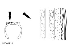
Inner edge (or shoulder) wear occurs on the inside edge of the tire and is usually caused by excessive toe out and/or excessive negative camber. If the tread depth of the outer shoulder is at least 50% greater than the tread depth of the inner shoulder, the tire is experiencing inner edge/shoulder wear. To determine whether tires have this type of wear, visually inspect the tires. In some instances, it may be necessary to measure the tread depth of each rib and compare it to that of the shoulder.
NOTE: RF tire shown, others similar.
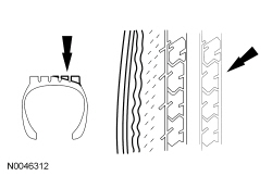
Outer edge (or shoulder) wear occurs on the outside edge of the tire and is usually caused by excessive toe in and/or excessive positive camber. If the tread depth of the inner shoulder is at least 50% greater than the tread depth of the outer shoulder, the tire is experiencing outer edge/shoulder wear. To determine whether tires have this type of wear, visually inspect the tires. In some instances, it may be necessary to measure the tread depth of each rib and compare it to that of the shoulder.
NOTE: RF tire shown, others similar.
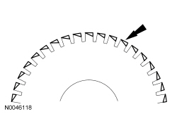
Heel/toe wear (also known as feathering) occurs along the outside or inside edge/shoulder of the tire. To determine whether tires have this type of wear, visually inspect the tires in both the inside and outside shoulder ribs. In some instances, it may be necessary to measure the difference in tread depth of leading versus trailing edge of each lug in the inside and outside shoulder rib.
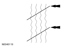
Diagonal wear occurs diagonally across the tread area and around the circumference of the tire. To determine whether tires have this type of wear, visually inspect the tires to determine if the wear pattern runs diagonally across the tread and around the circumference of the tire. In some instances, the difference in tread depth along the diagonal wear pattern may need to be measured.
Symptom Chart — Tire Wear
| Condition | Possible Sources | Action |
|---|---|---|
|
| |
| ||
| ||
|
| |
| ||
| ||
|
|
|
|
| |
| ||
|
|
Symptom Chart — NVH
| Condition | Possible Sources | Action |
|---|---|---|
|
|
|
|
| |
|
| |
|
|
|
|
|
|
Pinpoint Tests
For a description of the various tire wear patterns, refer to Inspection and Verification.
Pinpoint Test A: Inner Edge/Shoulder Wear
| Test Step | Result / Action to Take |
|---|---|
| A1 MEASURE THE TREAD DEPTH | |
| Yes
ROTATE the wheel and tire assemblies. CHECK and ADJUST the toe to nominal +0.15 degrees (toe in). CHECK and ADJUST caster and camber to nominal. REFER to Section 204-00 . No INSTALL a new tire(s). CHECK and ADJUST the toe to nominal. CHECK and ADJUST caster and camber to nominal. REFER to Section 204-00 . |
Pinpoint Test B: Outer Edge/Shoulder Wear
| Test Step | Result / Action to Take |
|---|---|
| B1 MEASURE THE TREAD DEPTH | |
| Yes
ROTATE the wheel and tire assemblies. CHECK and ADJUST the toe to nominal -0.15 degrees (toe out). CHECK and ADJUST caster and camber to nominal. REFER to Section 204-00 . No INSTALL a new tire(s). CHECK and ADJUST the toe to nominal. CHECK and ADJUST caster and camber to nominal. REFER to Section 204-00 . |
Pinpoint Test C: Diagonal Wear
| Test Step | Result / Action to Take |
|---|---|
| C1 MEASURE THE TREAD DEPTH | |
| Yes
If no performance concerns (noise/vibration) are present, the tire can remain in service. CHECK the air pressure in the tires, ADJUST as necessary. ROTATE the wheel and tire assemblies. INSPECT for loose, worn or damaged suspension components. INSTALL new components as necessary. CHECK the alignment and ADJUST as necessary. REFER to Section 204-00 . No INSTALL a new tire(s). CHECK the air pressure in the tires, ADJUST as necessary. ROTATE the wheel and tire assemblies. INSPECT for loose, worn or damaged suspension components. INSTALL new components as necessary. CHECK the alignment and ADJUST as necessary. REFER to Section 204-00 . |
Component Tests
Radial Runout
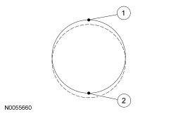
Radial runout is the egg-shaped deviation from a perfect circle and is measured perpendicular to the circumference. On a wheel and tire assembly, this means measuring the center tire tread rib. The center rib is indicative of the condition of the tire as a whole. Total runout is the difference between the maximum-to-minimum gauge reading. The high spot is the location of maximum runout.
| Item | Description |
|---|---|
| 1 | High spot |
| 2 | Low spot |
Loaded Runout Measurement (Hunter Road Force® 9700 Series Wheel Balancer)
NOTE: Diagnosis of tire/wheel vibration should not be performed on tires with less than 320 km (200 mi). Some initial tire/wheel vibration issues (such as flat spotting) may correct themselves after the tires have been in service for 320 km (200 mi).
This procedure is intended to assist with the diagnosis of wheel and tire assembly runout and/or force variation issues.
The Hunter Road Force® 9700 Series Wheel Balancer measures the wheel and tire assembly's loaded runout and the tire's radial spring rate. The balancer then converts the runout into pounds of force (termed as Road Force®). Measuring loaded runout (Road Force®) is more effective than measuring unloaded runout using a dial indicator.
NOTE: Use only the Digital Tire Gauge any time tire pressures are measured to be sure that accurate values are obtained.
Make sure that the tire pressures are set to the correct pressure as indicated on the Vehicle Certification (VC) label.NOTICE: Make sure that the correct wheel balancer adapters are used when mounting the assembly to the wheel balancer or damage to the wheel may occur.
NOTE: Make sure that the wheel and tire assembly is clean and free of foreign material prior to installation on the balancer.
NOTE: The wheel balancer inflation station must be turned OFF for tires with inflation pressures of 414 kPa (60 psi) or above.
Mount the wheel and tire assembly on a suitable wheel balancer using the correct wheel balancer adapters as shown. Refer to the list of recommended wheel balancer adapters on the PTS website.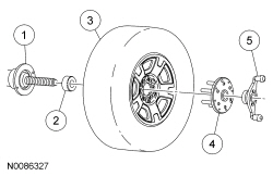
| Item | Description |
|---|---|
| 1 | Wheel balancer |
| 2 | Cone |
| 3 | Wheel and tire assembly |
| 4 | Finger plate |
| 5 | Balancer wing nut |
Runout Measurement (Dial Indicator)
NOTE: Diagnosis of tire/wheel vibration should not be performed on tires with less than 320 km (200 mi). Some initial tire/wheel vibration issues (such as flat spotting) will correct themselves after the tires have been in service for 320 km (200 mi).
NOTE: Loaded run-out measurements are the preferred method for verifying tire serviceability. While a dial indicator can be used to optimize the position of the tire on the wheel, the unloaded run-out measurement cannot accurately determine if the tire should be removed from service.
The following procedures should be used if normal diagnostics leads to a potential runout issue.
Some vehicles may exhibit a wheel and tire vibration caused by excessive runout. Radial runout measurements can be taken using a dial indicator and should be measured with the wheel and tire assembly mounted on a suitable wheel balancer. The dial indicator should be mounted securely to eliminate gauge movement when measuring runout.
NOTE: Use only the Digital Tire Gauge any time tire pressures are measured to be sure that accurate values are obtained.
Make sure that the tire pressures are set to the correct pressure as indicated on the VC label.NOTICE: Make sure that the correct wheel balancer adapters are used when mounting the assembly to the wheel balancer or damage to the wheel may occur.
NOTE: Make sure that the wheel and tire assembly is clean and free of foreign material prior to installation on the balancer.
Mount the wheel and tire assembly on a suitable wheel balancer using the correct wheel balancer adapters as shown. Refer to the list of recommended wheel balancer adapters on the PTS website.| Item | Description |
|---|---|
| 1 | Wheel balancer |
| 2 | Cone |
| 3 | Wheel and tire assembly |
| 4 | Finger plate |
| 5 | Balancer wing nut |
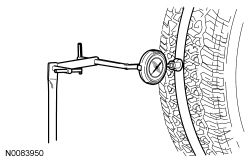
NOTE: Masking tape can be applied on the center tread rib to allow for a smoother measuring surface. Some fluctuation of the gauge reading is expected. Observe the overall sweep of the gauge from the highest to the lowest spot on the tire.
Position a suitable dial indicator and stand with the dial indicator on the center tread rib.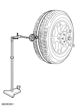
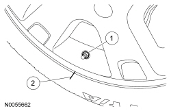
Match Mounting
NOTE: Road Force® values in illustrations are shown in pounds.
Match mounting is a technique used to reduce radial runout or road force on wheel and tire assemblies. Excessive runout is a source of ride quality complaints and match mounting can be used to minimize the runout. Match mounting can be accomplished by changing the position of the tire on the wheel.
| Item | Description |
|---|---|
| 1 | Valve stem |
| 2 | Reference mark |
NOTICE: For vehicles equipped with a Tire Pressure Monitoring System (TPMS), the sensor may be damaged by incorrect tire mounting or dismounting. Dismount the tire from the wheel as instructed in the Disassembly and Assembly procedure. Failure to follow these instructions may result in TPMS component damage.
NOTE: Always make sure that the final high spot and measurement values are permanently marked on the inward sidewall of the tire for reference during future wheel and tire service.
Using a suitable tire machine, separate the tire beads from the wheel.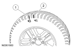
| Item | Description |
|---|---|
| 1 | First high spot on the tire |
| 2 | Second high spot on the tire |
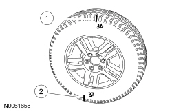
| Item | Description |
|---|---|
| 1 | First high spot on the tire |
| 2 | Second high spot on the tire |
NOTE: If the second high spot did not follow the wheel or the tire and the runout is still not within specification, improvements may be made by rotating the tire 90 degrees (one-fourth turn).
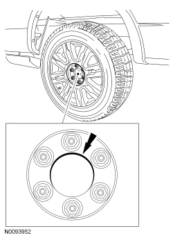
Draw an arrow on the tire sidewall from the second high spot towards the first high spot (in the shortest direction).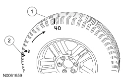
| Item | Description |
|---|---|
| 1 | First high spot on the tire |
| 2 | Second high spot on the tire |
Wheel-to-Hub Optimization
Wheel-to-hub optimization is important. Clearance between the wheel and hub can be used to offset or neutralize the Road Force® or run-out of the wheel and tire assembly. For every 0.001 inch of wheel-to-hub clearance, the Road Force® can be affected between 1 and 3 pounds depending on the tire stiffness.
NOTE: The example below illustrates how the clearance between the wheel and the hub can be used to offset the high spot of radial run-out or Road Force®. Following the procedure will make sure of the best optimization.
NOTE: Do not allow the full weight of the vehicle to rest on the tires while tightening the wheel nuts.
Lower the vehicle until the tires make contact with the ground, slightly loading the suspension. Tighten the wheel nuts as described in Wheel and Tire in this section.