SECTION 205-00: Driveline System — General Information
| 2014 Mustang Workshop Manual
|
DIAGNOSIS AND TESTING
| Procedure revision date: 01/07/2013
|
Differential Cooler
DTC Chart
Diagnostics in this manual assume a certain skill level and knowledge of Ford-specific diagnostic practices. Refer to Diagnostic Methods in
Section 100-00
for information about these practices.
PCM DTC Chart
Symptom Chart
Diagnostics in this manual assume a certain skill level and knowledge of Ford-specific diagnostic practices. Refer to Diagnostic Methods in
Section 100-00
for information about these practices.
Symptom Chart
| Condition
| Possible Sources
| Action
|
|---|
- The PCM does not respond to the scan tool
| - Fuse(s)
- Wiring, terminals or connectors
- PCM
| |
- The differential oil pump never runs
| - Fuse(s)
- Wiring, terminals or connectors
- Temperature sensor
- Differential oil pump relay
- Differential oil pump
- PCM
| - RETRIEVE and RECORD all PCM DTCs. REFER to the PCM DTC Chart. If there are no DTCs present,
GO to Pinpoint Test D
.
|
- The differential oil pump runs continuously
| - Wiring, terminals or connectors
- Temperature sensor
- Differential oil pump relay
- PCM
| - RETRIEVE and RECORD all PCM DTCs. REFER to the PCM DTC Chart. If there are no DTCs present,
GO to Pinpoint Test D
.
|
Diagnostic Routines
Pinpoint Test A: DTC P1888
Refer to Wiring Diagrams Cell
25
, Electronic Engine Controls - 5.8L for schematic and connector information.
Normal Operation and Fault Conditions
The temperature sensor is hardwired to the PCM. The PCM utilizes a fixed resistor (pull-up resistor) in series with the temperature sensor to monitor the entire temperature sensor circuit. As the differential oil temperature changes, the resistance in the temperature sensor changes which causes a variation in total circuit current flow resulting in a varying voltage drop across the pull-up resistor. The voltage signal used by the PCM to determine oil temperature is equal to the reference voltage minus the voltage drop across the pull-up resistor. Any circuit faults in the temperature sensor circuits or in the temperature sensor cause the PCM to set a DTC.
DTC Fault Trigger Conditions
| DTC
| Description
| Fault Trigger Conditions
|
|---|
| Differential Oil Temperature Sensor Circuit Failure
| This DTC sets in continuous memory and on-demand when the PCM detects a short to ground or an open in one or both of the temperature sensor circuits or in the sensor.
|
Possible Causes
- Wiring, terminals or connectors
- Differential oil temperature sensor
- PCM
Visual Inspection and Diagnostic Pre-checks
- Inspect the differential oil temperature sensor for any obvious signs of damage.
- Make sure the differential oil temperature sensor electrical connector is connected.
PINPOINT TEST A: DTC P1888
| Test Step
| Result / Action to Take
|
|---|
|
A1 CHECK THE TEMPERATURE SENSOR CIRCUITS FOR A SHORT TO VOLTAGE
|
|
- Ignition OFF.
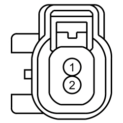
- Disconnect: Differential Oil Temperature Sensor C379.
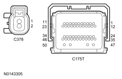
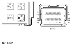
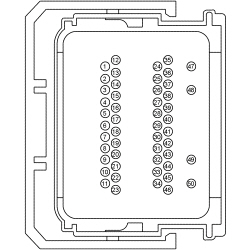
- Disconnect: PCM C175T.
- Ignition ON.
- Measure the
voltage
between:
| Positive Lead
| Negative Lead
| | Pin
| Circuit
| Pin
| Circuit
| | C379-1
| VET66 (GN)
| —
| Ground
| | C379-2
| RE406 (GY/VT)
| —
| Ground
|
 - Is any voltage present?
| Yes
REPAIR the affected circuit(s).
No
GO to
A2
.
|
|
A2 CHECK THE TEMPERATURE SENSOR CIRCUITS FOR A SHORT TO GROUND
|
|
- Ignition OFF.
- Measure the
resistance
between:
| Positive Lead
| Negative Lead
| | Pin
| Circuit
| Pin
| Circuit
| | C379-1
| VET66 (GN)
| —
| Ground
| | C379-2
| RE406 (GY/VT)
| —
| Ground
|
- Are the resistances greater than 10,000 ohms?
| Yes
GO to
A3
.
No
REPAIR the affected circuit(s).
|
|
A3 CHECK THE TEMPERATURE SENSOR CIRCUITS FOR AN OPEN
|
|
- Measure the
resistance
between:
| Positive Lead
| Negative Lead
| | Pin
| Circuit
| Pin
| Circuit
| | C379-1
| VET66 (GN)
| C175T-20
| VET66 (GN)
| | C379-2
| RE406 (GY/VT)
| C175T-38
| RE406 (GY/VT)
|
 - Are the resistances less than 3 ohms?
| Yes
GO to
A4
.
No
REPAIR the affected circuit(s).
|
|
A4 CHECK THE TEMPERATURE SENSOR CIRCUITS FOR A SHORT TOGETHER
|
|
- Measure the
resistance
between:
| Positive Lead
| Negative Lead
| | Pin
| Circuit
| Pin
| Circuit
| | C379-1
| VET66 (GN)
| C379-2
| RE406 (GY/VT)
|
- Is the resistance greater than 10,000 ohms?
| Yes
GO to
A5
.
No
REPAIR the affected circuit(s).
|
|
A5 CHECK THE PCM TEMPERATURE SENSOR OUTPUT
|
|
- Connect: PCM C175T.
- Ignition ON.
- Measure the
voltage
between:
| Positive Lead
| Negative Lead
| | Pin
| Circuit
| Pin
| Circuit
| | C379-1
| VET66 (GN)
| —
| Ground
|
- Is the voltage approximately 5 volts?
| Yes
INSTALL a new differential oil temperature sensor.
No
GO to
A6
.
|
|
A6 CHECK THE PCM FOR CORRECT OPERATION
|
|
- Ignition OFF.
- Disconnect and inspect all PCM electrical connectors.
- Repair:
- corrosion (install new connector or terminals — clean module pins)
- damaged or bent pins — install new terminals/pins
- pushed-out pins — install new pins as necessary
- Connect all PCM electrical connectors, make sure all connectors seat and latch correctly.
- operate the system and determine if the concern is still present.
- Is the concern still present?
| Yes
CHECK
for any applicable TSBs. If a TSB exists for this concern, DISCONTINUE this test and FOLLOW the TSB instructions. If no TSBs address this concern, INSTALL a new PCM. REFER to
Section 303-14
.
No
The system is operating correctly at this time. The concern may have been caused by module connections. ADDRESS the root cause of any connector or pin issues.
|
Pinpoint Test B: DTC P1889 or P188A
Refer to Wiring Diagrams Cell
25
, Electronic Engine Controls - 5.8L for schematic and connector information.
Normal Operation and Fault Conditions
When the differential oil temperature reaches a predetermined level, the PCM grounds the differential oil pump relay which activates the differential oil pump. Once the oil temperature is reduced to another predetermined level, the PCM stops grounding the relay. While the relay is activated, the PCM continues to monitor the differential oil temperature and expects to see a reduction in the temperature. If the PCM does not see a reduction in the temperature or if the temperature continues to rise, a DTC is set. Blocked air flow through the oil cooler, a blockage or restriction in the cooling hoses/tubes or an inoperative oil pump all contribute to poor cooling system performance.
DTC Fault Trigger Conditions
| DTC
| Description
| Fault Trigger Conditions
|
|---|
| Oil Pressure Pump Performance
| This DTC sets in continuous memory when the differential oil temperature exceeds system capability due to blockage, a component failure or system failure.
|
| Differential Oil Temperature Too High / Too Low
| This DTC sets in continuous memory when the differential oil temperature exceeds 145° C (293° F).
|
Possible Causes
- Restricted air flow through the oil cooler
- Restricted oil flow through the cooler system
- Fuse
- Wiring, terminals or connectors
- Differential oil pump relay
- Differential oil temperature sensor
- Differential oil pump
Visual Inspection and Diagnostic Pre-checks
- Make sure the differential oil is at the correct level.
- Make sure the differential and differential cooler system are free of any leaks.
- Make sure there are no air flow blockages or restrictions through the oil cooler.
PINPOINT TEST B: DTC P1889 OR P188A
| Test Step
| Result / Action to Take
|
|---|
|
B1 CHECK FOR OTHER PCM DTCS
|
|
- Ignition ON.
- Using a scan tool, carry out the PCM
self-test.
- Is DTC P1888 or P188E present?
| Yes
For DTC P1888,
GO to Pinpoint Test A
.
For DTC P188E,
GO to Pinpoint Test C
.
No
For all other PCM DTCs, REFER to
Section 303-14
.
If no other PCM DTCs are present, GO to
B2
.
|
|
B2 CHECK THE DIFFERENTIAL OIL PUMP OPERATION
|
|
- Using a scan tool, toggle the rear differential fluid pump (R_DIFF_PUMP)
ON.
- Does the pump motor run?
| Yes
TOGGLE the R_DIFF_PUMP
OFF. GO to
B3
.
No
TOGGLE the R_DIFF_PUMP
OFF.
GO to Pinpoint Test D
.
|
|
B3 CHECK THE DIFFERENTIAL COOLER SYSTEM FOR BLOCKAGES AND RESTRICTIONS
|
|
- Inspect the following items for damage, blockages or restrictions:
- Oil cooler
- Oil cooler fins
- Oil cooler hoses
- Differential outlet port
- Differential inlet port
- Is any damage, blockages or restrictions present?
| Yes
REPAIR or INSTALL new components as necessary.
No
INSTALL a new differential cooler oil pump. REFER to
Section 205-02
.
|
Pinpoint Test C: DTC P188E
Refer to Wiring Diagrams Cell
25
, Electronic Engine Controls - 5.8L for schematic and connector information.
Normal Operation and Fault Conditions
When the differential oil temperature reaches a predetermined level, the PCM grounds the differential oil pump relay which activates the differential oil pump. Once the oil temperature is reduced to another predetermined level, the PCM stops grounding the relay.
DTC Fault Trigger Conditions
| DTC
| Description
| Fault Trigger Conditions
|
|---|
| Oil Pressure Pump Control Circuit
| This DTC sets in continuous memory and on-demand when the PCM detects a short to ground or an open in the differential oil pump relay control circuit. Also, an open in the relay, the relay power supply circuit or
fuse 46 (5A) also cause this DTC to set.
|
Possible Causes
- Fuse
- Wiring, terminals or connectors
- Differential oil pump relay
- PCM
Visual Inspection and Diagnostic Pre-checks
- Make sure
fuse 46 (5A) is OK.
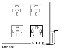
- Make sure the differential oil pump relay is present and fully seated in the
.
PINPOINT TEST C: DTC P188E
| Test Step
| Result / Action to Take
|
|---|
|
C1 CHECK THE VOLTAGE TO THE DIFFERENTIAL OIL PUMP RELAY
|
|
- Ignition OFF.
- Disconnect: Differential Oil Pump Relay.
- Measure the
voltage
between:
| Positive Lead
| Negative Lead
| | Pin
| Circuit
| Pin
| Circuit
| | Relay Cavity 1
| CBB46 (WH/BU)
| —
| Ground
|
 - Is the voltage greater than 11 volts?
| Yes
GO to
C2
.
No
VERIFY
fuse 46 (5A) is OK.
If OK, REPAIR the circuit.
If not OK, REFER to the Wiring Diagrams Manual to identify the possible causes of the circuit short.
|
|
C2 CHECK THE DIFFERENTIAL OIL PUMP RELAY
|
|
| Yes
GO to
C3
.
No
INSTALL a new relay.
|
|
C3 CHECK THE DIFFERENTIAL OIL PUMP RELAY CONTROL CIRCUIT FOR AN OPEN
|
|
- Measure the
resistance
between:
| Positive Lead
| Negative Lead
| | Pin
| Circuit
| Pin
| Circuit
| | Relay Cavity 1
| CBB46 (WH/BU)
| C175T-2
| CBB46 (WH/BU)
|
 - Are the resistances less than 3 ohms?
| Yes
GO to
C4
.
No
INSPECT in-line connector C110 for corrosion, bent pins and pushed-out terminals. VERIFY in-line connector C110 is fully seated and connected. REPAIR or INSTALL new as necessary.
If in-line connector C110 is OK, REPAIR the circuit.
|
|
C4 CHECK THE DIFFERENTIAL OIL PUMP RELAY CONTROL CIRCUIT FOR A SHORT TO GROUND
|
|
- Measure the
resistance
between:
| Positive Lead
| Negative Lead
| | Pin
| Circuit
| Pin
| Circuit
| | C175T-2
| CE621 (YE/GY)
| —
| Ground
|
 - Is the resistance greater than 10,000 ohms?
| Yes
GO to
C5
.
No
REPAIR the affected circuit.
|
|
C5 CHECK THE PCM FOR CORRECT OPERATION
|
|
- Ignition OFF.
- Disconnect and inspect all PCM electrical connectors.
- Repair:
- corrosion (install new connector or terminals — clean module pins)
- damaged or bent pins — install new terminals/pins
- pushed-out pins — install new pins as necessary
- Connect all PCM electrical connectors, make sure all connectors seat and latch correctly.
- operate the system and determine if the concern is still present.
- Is the concern still present?
| Yes
CHECK
for any applicable TSBs. If a TSB exists for this concern, DISCONTINUE this test and FOLLOW the TSB instructions. If no TSBs address this concern, INSTALL a new PCM. REFER to
Section 303-14
.
No
The system is operating correctly at this time. The concern may have been caused by module connections. ADDRESS the root cause of any connector or pin issues.
|
Pinpoint Test D: The Differential Cooler Pump Never Runs Or Runs Continuously
Refer to Wiring Diagrams Cell
25
, Electronic Engine Controls - 5.8L for schematic and connector information.
Normal Operation and Fault Conditions
When the differential oil temperature reaches a predetermined level, the PCM grounds the differential oil pump relay which activates the differential oil pump. Once the oil temperature is reduced to another predetermined level, the PCM stops grounding the relay.
Possible Causes
- Fuse
- Wiring, terminals or connectors
- Differential oil pump relay
- PCM
Visual Inspection and Diagnostic Pre-checks
- Make sure
fuses 46 (5A) and 12 (20A) are OK.
- Make sure the differential oil pump relay is present and fully seated in the
.
PINPOINT TEST D: THE DIFFERENTIAL COOLER PUMP NEVER RUNS OR RUNS CONTINUOUSLY
| Test Step
| Result / Action to Take
|
|---|
|
D1 CHECK THE DIFFERENTIAL OIL PUMP OPERATION
|
|
- Ignition ON.
- Listen for differential oil pump operation.
- Is the differential oil pump operating?
| Yes
GO to
D2
.
No
GO to
D3
.
|
|
D2 CHECK THE DIFFERENTIAL OIL PUMP RELAY
|
|
- Disconnect: Differential Oil Pump Relay.
- Is the differential oil pump still operating?
| Yes
REPAIR circuit CYT14 (VT/OG) for a short to voltage.
No
INSTALL a new relay.
|
|
D3 CHECK THE VOLTAGE TO THE DIFFERENTIAL OIL PUMP RELAY
|
|
- Ignition OFF.
- Disconnect: Differential Oil Pump Relay.
- Measure the
voltage
between:
| Positive Lead
| Negative Lead
| | Pin
| Circuit
| Pin
| Circuit
| | Relay Cavity 1
| CBB46 (WH/BU)
| —
| Ground
| | Relay Cavity 3
| SBB12 (GN/RD)
| —
| Ground
|
- Are the voltages greater than 11 volts?
| Yes
GO to
D4
.
No
VERIFY
fuse 46 (5A) is OK.
If OK, REPAIR circuit CBB46 (WH/BU).
VERIFY
fuse 12 (20A) is OK.
If OK, REPAIR circuit SBB12 (GN/RD).
If either fuse is not OK, REFER to the Wiring Diagrams Manual to identify the possible causes of the circuit short.
|
|
D4 CHECK THE DIFFERENTIAL PUMP VOLTAGE SUPPLY CIRCUIT FOR A SHORT TO GROUND
|
|
- Measure the
resistance
between:
| Positive Lead
| Negative Lead
| | Pin
| Circuit
| Pin
| Circuit
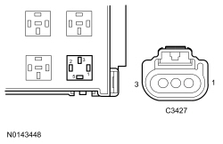
| | C3427-1
| CYT14 (VT/OG)
| —
| Ground
| | C3427-2
| CYT14 (VT/OG)
| —
| Ground
|
 - Is the resistance greater than 10,000 ohms?
| Yes
GO to
D5
.
No
REPAIR the circuit.
|
|
D5 CHECK THE DIFFERENTIAL PUMP VOLTAGE SUPPLY CIRCUIT FOR AN OPEN
|
|
- Measure the
resistance
between:
| Positive Lead
| Negative Lead
| | Pin
| Circuit
| Pin
| Circuit
| | Relay Cavity 5
| CYT14 (VT/OG)
| C3427-1
| CYT14 (VT/OG)
| | Relay Cavity 5
| CYT14 (VT/OG)
| C3427-2
| CYT14 (VT/OG)
|
 - Is the resistance less than 3 ohms?
| Yes
GO to
D6
.
No
INSPECT in-line connector C237 for corrosion, bent pins and pushed-out terminals. VERIFY in-line connector C237 is fully seated and connected. REPAIR or INSTALL new as necessary.
If in-line connector C237 is OK, REPAIR the circuit.
|
|
D6 CHECK THE DIFFERENTIAL PUMP GROUND CIRCUIT FOR AN OPEN
|
|
- Measure the
resistance
between:
| Positive Lead
| Negative Lead
| | Pin
| Circuit
| Pin
| Circuit
| | C3427-3
| GD171 (BK/GY)
| —
| Ground
|
- Is the resistance less than 3 ohms?
| Yes
INSTALL a new differential cooler fluid pump. REFER to
Section 205-02
.
No
REPAIR the circuit.
|