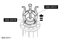
SECTION 205-02: Rear Drive Axle/Differential — Ford 8.8-Inch Ring Gear
2014 Mustang Workshop Manual
IN-VEHICLE REPAIR
Procedure revision date: 01/07/2013

Differential Ring And Pinion


Special Tool(s)
2 Jaw Puller
205-D072 (D79L-4221-A1) or equivalent
Adapter for 205-S127
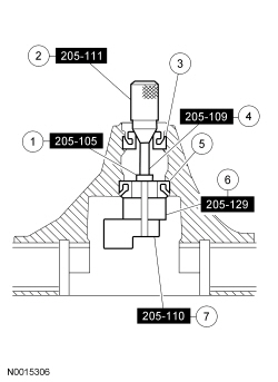
205-105 (T76P-4020-A3)
Adapter for 205-S127
205-109 (T76P-4020-A9)
Adapter for 205-S127
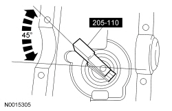
205-110 (T76P-4020-A10)
Adapter for 205-S127
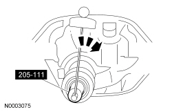
205-111 (T76P-4020-A11)
Adapter for 205-S127
205-129 (T79P-4020-A18)
Adapter for 205-S127
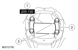
205-130 (T79P-4020-A19)
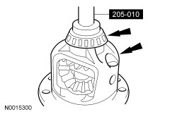
Installer, Differential Side Bearing
205-010 (T57L-4221-A2)
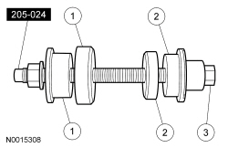
Installer, Drive Pinion Bearing Cup
205-024 (T67P-4616-A)
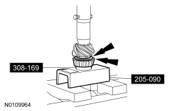
Installer, Shaft Bearing Cone
308-169 (T88T-7025-B)
Plate, Bearing Oil Seal
205–090 (T75L-1165–B)
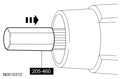
Protector, Drive Pinion Thread
205-460 or equivalent
Step Plate
205-D016 (D80L-630-5) or equivalent
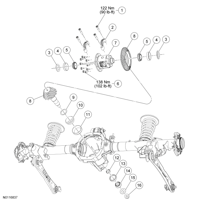
Material
Item Specification
Maximum Strength Retaining Compound
Loctite® 638™


Item Part Number Description
1 Differential bearing cap bolt (part of 4010)
2 Differential bearing cap (part of 4010)
3 4067 Differential bearing shims (2 required)
4 4221 Differential bearing cups (2 required)
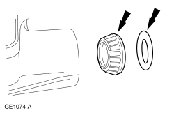
5 4222 Differential bearing cones (2 required)
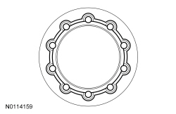
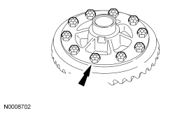
6 4216 Differential ring gear bolt (10 required)
7 Differential carrier assembly
8 4209 Ring gear (set with drive pinion)
9 4663 Pinion bearing adjustment shim
10 4630 Inner pinion bearing
11 4628 Inner pinion bearing cup
12 4662 Collapsible spacer
13 4616 Outer pinion bearing cup
14 4621 Outer pinion bearing
15 4670 Pinion oil slinger
16 4320 Pinion nut

Removal

  1. Remove the drive pinion flange seal. For additional information, refer to Drive Pinion Flange and Drive Pinion Seal in this section.
  1. Remove the differential carrier. For additional information, refer to Differential Carrier in this section.
  1. Remove and discard the 10 differential ring gear bolts.
  1. NOTE: Do not damage the differential ring gear bolt hole threads.

    Insert a punch in the differential ring gear bolt holes and drive the differential ring gear off.
  1. NOTE: The differential flange and ring gear flange must be free of any old retaining compound material. Failure to clean the surfaces can result in ring gear runout concerns.

    Clean all traces of the old retaining compound material from the differential flange.
  1. Using the 2 Jaw Puller and Step Plate, remove the 2 differential bearings.
  1. Remove the drive pinion shaft oil slinger and the outer drive pinion bearing.
  1. Install the Drive Pinion Thread Protector. Using a soft-faced hammer, drive the pinion assembly out of the axle housing.
  1. Remove and discard the drive pinion collapsible spacer.
  1. Using a brass drift, remove the drive pinion bearing cups by tapping alternately on opposite sides of the drive pinion bearing cups.

Installation

  1. Position the Drive Pinion Bearing Cup Installer and the inner and outer drive pinion bearing cups in their respective bores.
    1. After placing the inner and outer drive pinion bearing cups in their bores, place the Drive Pinion Bearing Cup Installer (inner) on the inner drive pinion bearing cup.
    1. Place the Drive Pinion Bearing Cup Installer (outer) on the outer drive pinion bearing cup.
    1. Install the Drive Pinion Bearing Cup Installer.
  1. Tighten the Drive Pinion Bearing Cup Installer to seat the drive pinion bearing cups into their bores.
  1. NOTE: If a feeler gauge can be inserted between a drive pinion bearing cup and the bottom of its bore at any point around the drive pinion bearing cup, the drive pinion bearing cup is not correctly seated.

    Make sure the drive pinion bearing cups are correctly seated in their bores.
  1. NOTE: Install new drive pinion bearings without any additional lubricant since the anti-rust oil provides adequate lubricant without upsetting the drive pinion bearing preload settings.

    Assemble and position the Adapters for 205-S127.


    Item Part Number Description
    1 205-105 Adapter for 205-S127 (1.612 inch OD) (T76P-4020-A3)
    2 205-111 Adapter for 205-S127 (T76P-4020-A11)
    3 4621 Drive pinion bearing (outer)
    4 205-109 Adapter for 205-S127 (T76P-4020-A9)
    5 4630 Drive pinion bearing (inner)
    6 205-129 Adapter for 205-S127 (1.1884 inch thick) (T79P-4020-A18)
    7 205-110 Adapter for 205-S127 (1.7 inch thick) (T76P-4020-A10)
  1. NOTE: This step duplicates final drive pinion bearing preload.

    Tighten the Adapter.
  1. NOTE: The Adapter must be offset to obtain an accurate reading.

    Rotate the Adapter several half-turns to make sure of correct seating of the drive pinion bearings.
  1. Install the Adapter.
    1. Position the Adapter.
    1. Install the 2 differential bearing caps.
    1. Install the 4 differential bearing cap bolts.
      • Tighten to 122 Nm (90 lb-ft).
  1. NOTE: Drive pinion bearing adjustment shims must be flat and clean.

    NOTE: A slight drag should be felt for correct drive pinion bearing adjustment shim selection. Do not attempt to force the drive pinion bearing adjustment shim between the gauge block and the gauge tube. This will minimize selection of a drive pinion bearing adjustment shim thicker than required, which results in a deep tooth contact in final assembly of integral axle assemblies.

    Use a drive pinion bearing adjustment shim as a gauge for drive pinion bearing adjustment shim selection.
  1. Using the Shaft Bearing Cone Installer and Bearing Oil Seal Plate with a shop press, drive the inner drive pinion bearing and the selected drive pinion bearing adjustment shim until they are firmly seated on the pinion shaft.
  1. Install a new drive pinion collapsible spacer on the pinion shaft against the pinion shaft shoulder.
  1. Install the drive pinion assembly into the axle housing.
  1. Install the outer drive pinion bearing and the drive pinion shaft oil slinger.
  1. Using the Differential Side Bearing Installer, install the 2 new differential bearings.
  1. Apply a one-eighth inch bead of maximum strength retaining compound on the rear face of the ring in the pattern shown.
  1. Using 2 ring gear bolts as a guide, press the ring gear on the differential assembly.
  1. Install the 10 new differential ring gear bolts.
  1. Install the drive pinion seal and flange. For additional information, refer to Drive Pinion Flange and Drive Pinion Seal in this section.
  1. Install the differential carrier. For additional information, refer to Differential Carrier in this section.