SECTION 307-01: Automatic Transaxle/Transmission — 6R80
| 2014 Mustang Workshop Manual
|
DESCRIPTION AND OPERATION
| Procedure revision date: 01/07/2013
|
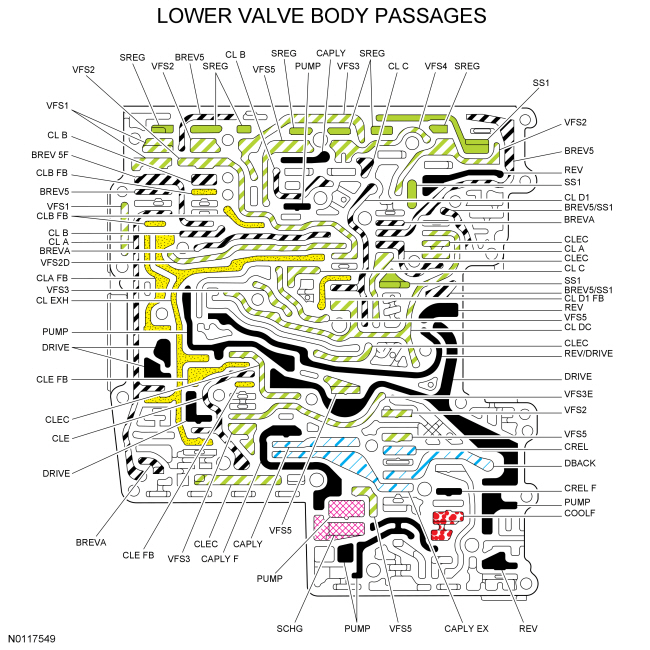
Hydraulic Circuit Identification and Function
Hydraulic Circuit Identification Chart
| Circuit Name | Description |
|---|---|
| BREVA | BREV5 pressure from the drive enable valve to the clutch A regulator valve. |
| BREV5 | BREV 5F pressure from the clutch A latch valve to the drive enable valve and the No. 2 shuttle ball. |
| BREV 5F | Regulated line pressure from the CL B circuit directed to the A clutch latch valve by the B clutch latch valve. |
| BREV5/SS1 | BREV5 or SS1 pressure from the No. 2 shuttle ball to the solenoid multiplex valve. |
| CAPLY | Apply circuit to the torque converter, also the return circuit during Torque Converter Clutch (TCC) release. |
| CAPLY EX | TCC release pressure from the bypass clutch control regulator valve to the converter release regulator valve. |
| CAPLY F | Line pressure from the PUMP circuit directed to the bypass clutch control regulator valve by the main regulator valve. |
| CL A | Regulated line pressure from the clutch A regulator valve to the clutch A latch valve and the forward (A) clutch to apply the clutch. |
| CLA FB | Regulated line pressure from the clutch A latch valve that feeds back to the clutch A regulator valve. |
| CL B | Regulated line pressure from the clutch B regulator valve to the clutch B latch valve and the direct (B) clutch to apply the clutch. |
| CLB FB | Regulated line pressure from the clutch B latch valve that feeds back to the clutch B regulator valve. |
| CL C | Regulated line pressure from the clutch C regulator valve to the intermediate (C) clutch to apply the clutch. |
| CL D1 | Regulated line pressure from the clutch D1 regulator valve to the clutch D1 latch valve and the low/reverse (D) clutch to apply the clutch. |
| CL D1 FB | Regulated line pressure from the clutch D1 latch valve that feeds back to the clutch D1 regulator valve. |
| CL DC | Regulated solenoid output pressure from Shift Solenoid D (SSD) directed by the solenoid multiplex valve to the D1 and D2 regulator and latch valves to apply the low/reverse (D) clutch. |
| CLE | Regulated line pressure from the clutch E regulator valve to the clutch E latch valve and the overdrive (E) clutch to apply the clutch. |
| CLEC | Regulated solenoid output pressure from the CLEC F circuit directed by the drive enable valve to the clutch E regulator and latch valves to apply the clutch. |
| CLEC F | Regulated solenoid output pressure from the VFS4 circuit directed to the drive enable valve by the solenoid multiplex valve to move the clutch E regulator and latch valves to apply the overdrive (E) clutch. |
| CLE FB | Regulated line pressure from the clutch E latch valve that feeds back to the clutch E regulator valve. |
| CL EXH | Line pressure regulated to approximately 21 kPa (3 psi) by the D2 latch valve that supplies exhaust pressure to the A, B, C, D1 and E clutch when the clutches are released. |
| COOLF | Pressure from the lubrication control valve to the oil cooler or the thermal bypass valve that feeds the lubrication circuit. |
| CREL | Pressure supplied to the torque converter by the converter release regulator valve to release the TCC . |
| CREL F | Line pressure from the main regulator valve that supplies the converter release regulator valve and the lubrication control valve. |
| DBACK | CAPLY EX pressure directed to the drain back valve by the converter release regulator valve. |
| DRIVE | Line pressure directed by the manual valve to the A, C and E clutch regulator valves and the No. 1 shuttle ball. |
| LUBE | Transmission lubrication circuit supplied by the COOLF circuit after the fluid circulates the transmission fluid cooler or is returned by the cooler bypass valve. |
| PUMP | Line pressure supplied by the pump to the manual valve, solenoid pressure regulator valve, main regulator valve, clutch D1 regulator valve, clutch D2 regulator valve and clutch D2 latch valve. |
| REV | Line pressure from the manual valve to the No. 1 shuttle ball and the solenoid multiplex valve. |
| REV/DRIVE | REV or DRIVE pressure from the No. 1 shuttle ball to the clutch B regulator valve. |
| SCHG | Line pressure from the main regulator valve to the pump suction port. |
| SREG | Line pressure from the solenoid regulator valve that supplies pressure to the 7 solenoids Shift Solenoid A (SSA), Shift Solenoid B (SSB), Shift Solenoid C (SSC), SSD , Shift Solenoid E (SSE), TCC solenoid and Line Pressure Control (LPC) solenoid. |
| SS1 | Solenoid output pressure from SSE to the drive enable valve and to shuttle ball No. 2. to direct SSD output pressure to clutch E regulator and latch valves to apply the overdrive (E) clutch. |
| VFS1 | Solenoid output pressure from SSA to the A clutch regulator and latch valve to apply the forward (A) clutch. |
| VFS2 | Solenoid output pressure from SSB to the B clutch regulator and latch valve to apply the direct (B) clutch and is also routed to the D1 latch valve. |
| VFS2D | SSB output pressure from the VFS2 circuit directed to the clutch B regulator valve by the D1 latch valve. |
| VFS3 | Solenoid output pressure from SSC to the C clutch regulator valve to apply the intermediate (C) clutch and is also routed to the clutch E latch valve. |
| VFS3E | SSC output pressure from the VFS3 circuit directed to the clutch C regulator valve by the clutch E latch valve. |
| VFS4 | Solenoid output pressure from SSD to the solenoid multiplex valve to apply either the D or E clutch. |
| VFS5 | Solenoid output pressure from the LPC solenoid to the main regulator valve to control line pressure. |
| VFS6 | Solenoid output pressure from the TCC solenoid to the bypass clutch control regulator valve and the converter release regulator valve to control the TCC . |
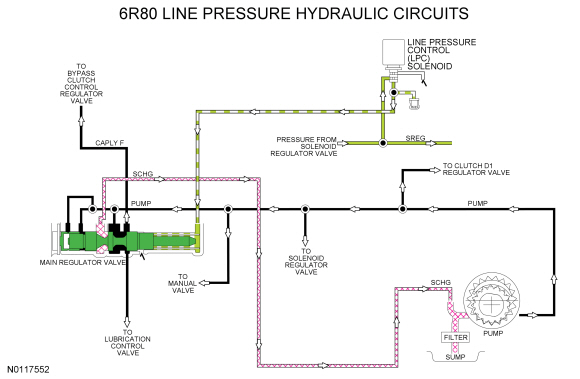
Line Pressure Hydraulic Circuits
The PCM controls line pressure with the Line Pressure Control (LPC) solenoid. Varying pressure from the LPC solenoid effects shift feel while allowing sufficient pressure for clutch application.
When the engine is running, the pump supplies pressure to the main regulator valve through the PUMP circuit. The position of the main regulator valve controls line pressure (in the PUMP circuit). Pressure from the LPC through the VFS5 circuit controls the position of the main regulator valve.
The main regulator valve varies pressure in the SCHG circuit. The higher the pressure in the SCHG circuit, the lower the line pressure (PUMP circuit) is. As SCHG pressure decreases, line pressure (PUMP circuit) increases.
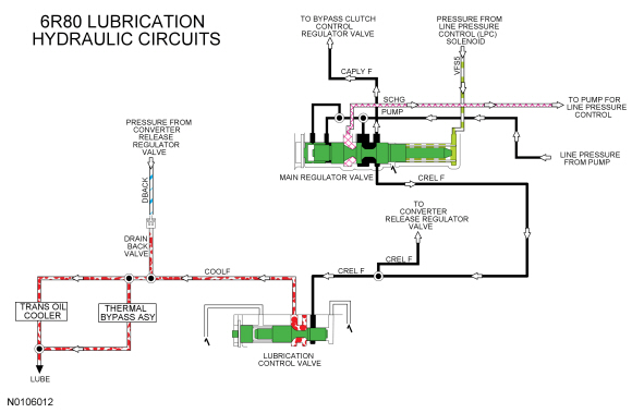
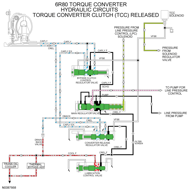
Lubrication Hydraulic Circuits
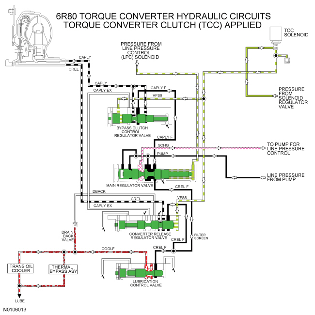
The main regulator valve supplies pressure to the lubrication control valve through the CREL F circuit. When the Torque Converter Clutch (TCC) is applied, the lubrication control valve supplies the transmission lubrication through the COOLF circuit to the LUBE circuit.
When the TCC is released, return fluid from the torque converter is supplied to the LUBE circuit through the CAPLY, CAPLY EX and DBACK circuits.
Pressure in the LUBE circuit either circulates through the thermal bypass valve when Transmission Fluid Temperature (TFT) is below operating temperature or through the transmission fluid cooler when the transmission fluid is at or above operating temperature. Return fluid from the thermal bypass valve or the transmission fluid cooler enters the input shaft through the pump assembly and flows through passages in the input shaft, intermediate shaft and output shaft to provide lubrication for the transmission.
Torque Converter Hydraulic Circuits
When the TCC is released, line pressure is supplied to the converter release regulator valve from the lubrication control valve through the CREL F circuit. The converter release regulator valve supplies pressure to the torque converter through the CREL circuit to release the torque converter.
CREL pressure exits the torque converter through the CAPLY circuit and goes to the bypass clutch control regulator valve. The bypass clutch control regulator valve directs the fluid back to the converter release regulator valve through the CAPLY EX circuit. The converter release regulator valve directs the fluid to the DBACK circuit where it supplies lubrication in the LUBE circuit.
When the TCC is applied, the TCC solenoid applies hydraulic pressure to the bypass clutch control regulator valve and the converter release regulator valve through the VFS6 circuit to position the valves to apply the TCC .
Line pressure is supplied to the bypass clutch control regulator valve from the main regulator valve. The bypass clutch control regulator valve directs regulated line pressure to the TCC through the CAPLY circuit to apply the TCC .
CAPLY pressure exits the torque converter through the CREL circuit and goes to the converter release regulator valve.
For torque converter description and function, refer to Torque Converter in this section.
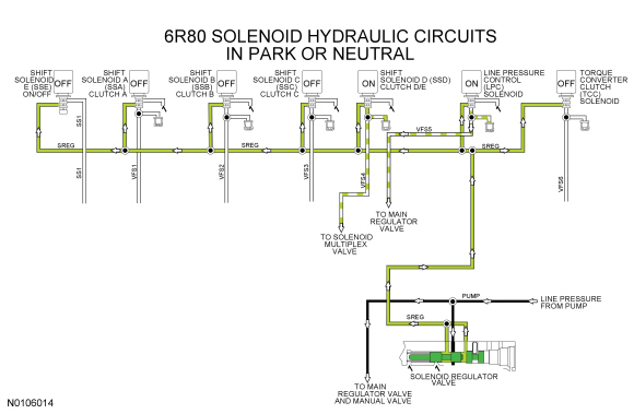
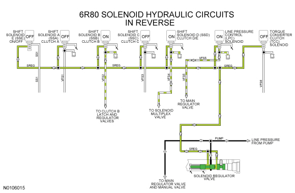
Solenoid Hydraulic Circuits
LINE pressure from the pump is directed to the individual shift, TCC solenoid and LPC solenoid by the solenoid regulator valve through the SREG circuit. The PCM controlled solenoids, direct full or regulated SREG pressure to the valves that they control.
For electrical operation of the solenoids, refer to Transmission Electronic Control System in this section.
The LPC solenoid sends varying pressure to the main regulator valve to control line pressure.
In the PARK and NEUTRAL position, the PCM supplies low current to Shift Solenoid D (SSD) to apply high-regulated pressure to the solenoid multiplex valve which directs the pressure to the D1 regulator and latch valves to apply the low/reverse clutch (D).
In the REVERSE position, the PCM supplies low current to Shift Solenoid B (SSB) to apply high-regulated pressure to the clutch B regulator and latch valves to apply the direct clutch (B). The PCM also supplies low current to SSD to apply high-regulated pressure to the solenoid multiplex valve which directs the pressure to the D1 regulator and latch valves to apply the low/reverse clutch (D).
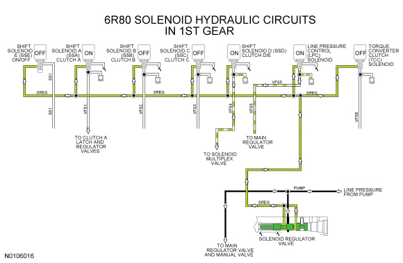
In 1st gear, the PCM supplies high current to Shift Solenoid A (SSA) to apply high-regulated pressure to the clutch A regulator and latch valves to apply the forward clutch (A). The PCM also supplies low current to SSD to apply high-regulated pressure to the solenoid multiplex valve which directs the pressure to the D1 regulator and latch valves to apply the low/reverse clutch (D).
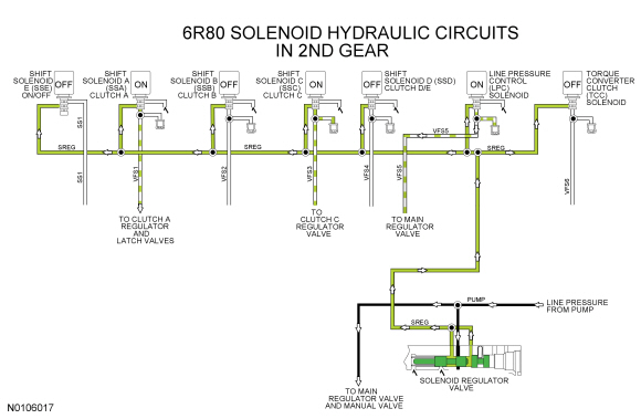
In 2nd gear, the PCM supplies high current to SSA to apply high-regulated pressure to the clutch A regulator and latch valves to apply the forward clutch (A). The PCM also supplies high current to Shift Solenoid C (SSC) to apply high-regulated pressure to the clutch C regulator valve to apply the intermediate clutch (C).
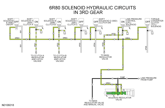
In 3rd gear, the PCM supplies high current to SSA to apply high-regulated pressure to the clutch A regulator and latch valves to apply the forward clutch (A). The PCM also supplies low current to Shift Solenoid B (SSB) to apply high-regulated pressure to the clutch B regulator and latch valves to apply the direct clutch (B).
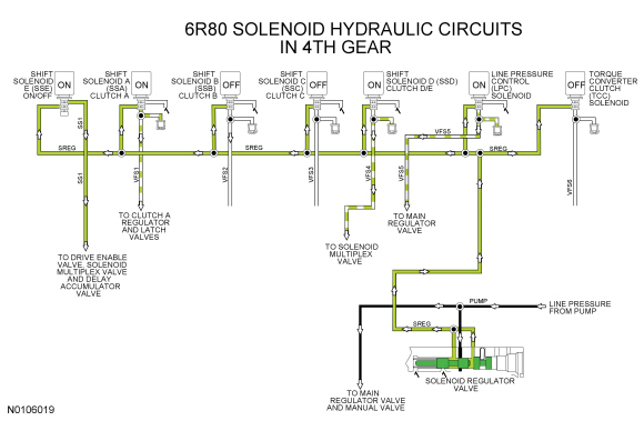
In 4th gear, the PCM supplies high current to SSA to apply high-regulated pressure to the clutch A regulator and latch valves to apply the forward clutch (A). The PCM also supplies low current to SSD to apply high-regulated pressure to the solenoid multiplex valve which directs the pressure to the clutch E regulator and latch valves to apply the overdrive clutch (E). The PCM turns on Shift Solenoid E (SSE) to apply pressure to the solenoid multiplex valve and the drive enable valve to direct SSD pressure to the clutch E regulator and latch valves.
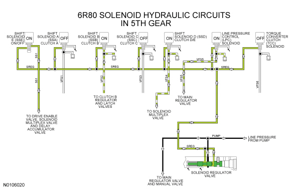
In 5th gear, the PCM supplies low current to SSD to apply high-regulated pressure to the solenoid multiplex valve which directs the pressure to the clutch E regulator and latch valves to apply the overdrive clutch (E). The PCM turns on SSE to apply pressure to the solenoid multiplex valve and the drive enable valve to direct SSD pressure to the clutch E regulator and latch valves. The PCM also supplies low current to SSB to apply high-regulated pressure to the clutch B regulator and latch valves to apply the direct clutch (B).
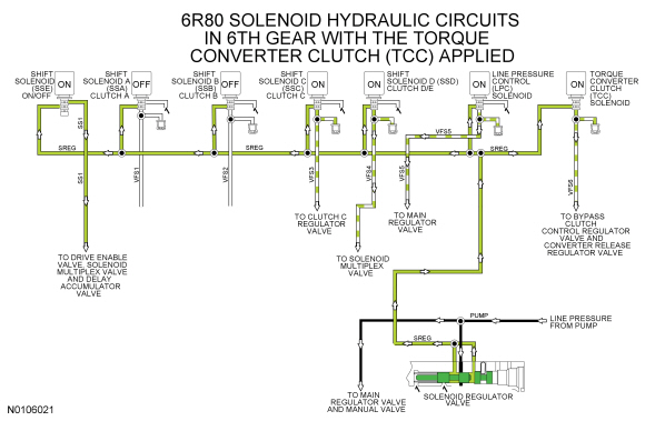
In 6th gear, the PCM supplies low current to SSD to apply high-regulated pressure to the solenoid multiplex valve which directs the pressure to the clutch E regulator and latch valves to apply the overdrive clutch (E). The PCM turns on SSE to apply pressure to the solenoid multiplex valve and the drive enable valve to direct SSD pressure to the clutch E regulator and latch valves. The PCM also supplies high current to SSC to apply high-regulated pressure to the clutch C regulator valve to apply the intermediate clutch (C). To apply the TCC , the PCM supplies high current to the TCC solenoid to apply high-regulated pressure to the converter release regulator valve and the bypass clutch control regulator valve to apply the TCC .
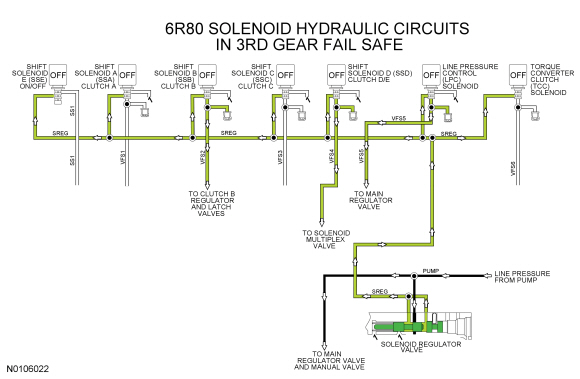
In 3rd gear fail safe, all solenoids are off. SSB , in the off position, applies high pressure to the clutch B regulator and latch valves to apply the direct clutch (B). The forward clutch (A) is hydraulically applied in 3rd gear fail safe. PCA provides maximum solenoid pressure to the main regulator valve for maximum line pressure. Also, SSD is on which applies high pressure to the solenoid multiplex valve which is directed to the drive enable valve where it is blocked.
Forward Clutch (A) Hydraulic Circuits
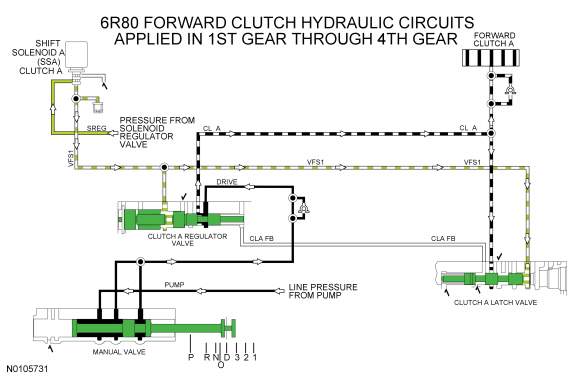
To apply the forward clutch (A), the manual valve must be in the DRIVE, 3, 2 or 1 position to provide line pressure to the clutch A regulator valve through the DRIVE circuit.
For the forward clutch (A) to apply, SSA provides regulated solenoid pressure from the SREG circuit to the clutch A regulator and latch valves through the VFS1 circuit to position the valves to apply the forward clutch (A). As the forward clutch is applied, SSA increases pressure to the clutch A regulator and latch valves.
The clutch A regulator valve provides regulated line pressure to the CL A circuit to apply the forward clutch (A).
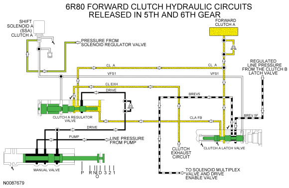
The forward clutch (A) is released when the manual valve is in the NEUTRAL, REVERSE or PARK position or the when the manual valve is in the DRIVE position with the transmission in 5th or 6th gear.
SSA lowers pressure to the clutch A regulator and latch valve to position the valves to lower the regulated line pressure in the CL A circuit to release the clutch.
When the forward clutch (A) is released, the clutch A regulator valve directs exhaust circuit pressure from the CL EXH circuit to the CL A circuit to fill the circuit and the forward clutch (A) with fluid at low pressure, approximately 21 kPa (3 psi).
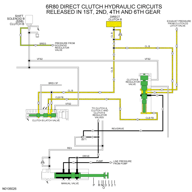
Direct Clutch (B) Hydraulic Circuits
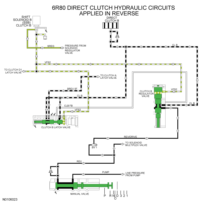
To apply the direct clutch (B), the manual valve can be in the REVERSE, DRIVE, 3, 2 or 1 position to provide line pressure to the clutch B regulator valve through the REV/DRIVE circuit.
For the direct clutch (B) to apply in reverse, SSB provides regulated solenoid pressure from the SREG circuit to the clutch B regulator and latch valves through the VFS2 circuit to position the valves to apply the direct clutch (B). As the direct clutch is applied, SSB increases pressure to the clutch B regulator and latch valves.
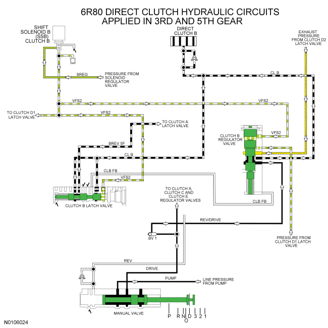
The clutch B regulator valve provides regulated line pressure to the CL B circuit to apply the direct clutch (B).
When the direct clutch (B) is applied in 3rd and 5th gear, regulated solenoid pressure from the D1 latch valve is supplied to the clutch B regulator valve through the VFS2D circuit and opposes pressure from the VFS2 circuit for clutch B valve positioning.
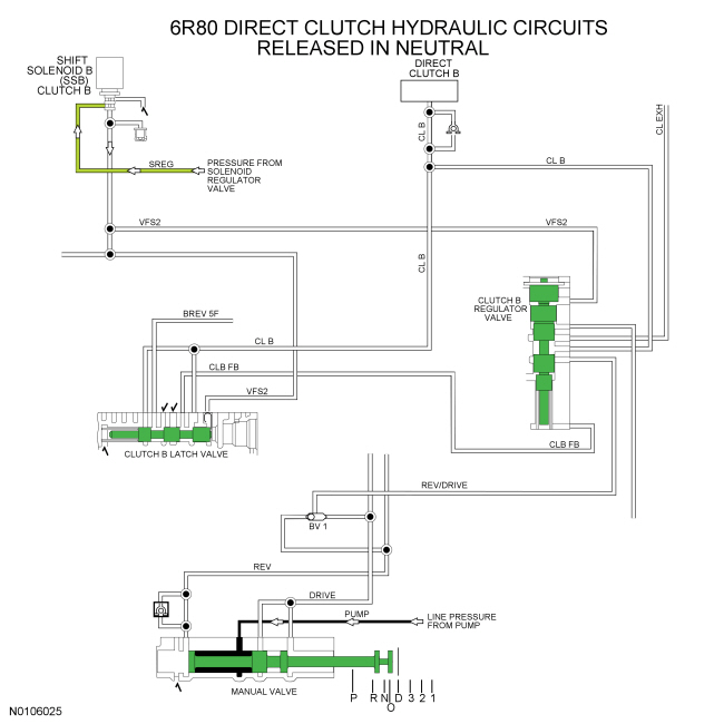
The direct clutch (B) is released when the manual valve is in the PARK or NEUTRAL position or when the manual valve is in the DRIVE position with the transmission in 1st, 2nd, 4th or 6th gear.
In NEUTRAL or PARK, the manual valve does not supply line pressure to the clutch B regulator valve. SSB lowers pressure to the clutch B regulator and latch valve to position the valves to lower the regulated line pressure in the CL B circuit to release the clutch.
In 1st, 2nd, 4th or 6th gear, the manual valve supplies line pressure to the clutch B regulator valve. SSB lowers pressure to the clutch B regulator and latch valve to position the valves to lower the regulated line pressure in the CL B circuit to release the clutch.
When the direct clutch (B) is released in 1st, 2nd, 4th or 6th gear, the clutch (B) regulator valve directs exhaust circuit pressure from the CL EXH circuit to the CL B circuit to fill the circuit and the direct clutch (B) with fluid at low pressure, approximately 21 kPa (3 psi).
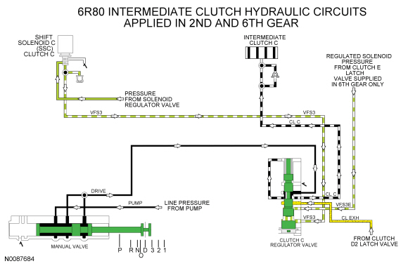
Intermediate Clutch (C) Hydraulic Circuits
To apply the intermediate clutch (C), the manual valve can be in the DRIVE, 3, 2 or 1 position to provide line pressure to the clutch C regulator valve through the DRIVE circuit.
SSC provides regulated solenoid pressure from the SREG circuit to the clutch C regulator valve through the VFS3 circuit to position the valve to apply the intermediate clutch (C). As the intermediate clutch (C) is applied, SSC increases pressure to the clutch C regulator valve.
The clutch C regulator valve provides regulated line pressure to the CL C circuit to apply the intermediate clutch (C).
Regulated solenoid pressure from the clutch E latch valve is supplied to the clutch C regulator valve through the VFS3E circuit and opposes VFS3 pressure for clutch C regulator valve positioning in 6th gear only.
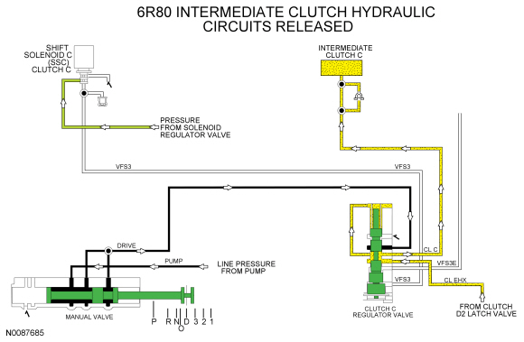
To release the intermediate clutch (C) when the manual valve is in the DRIVE, 3, 2 or 1 position SSC lowers pressure to the clutch C regulator valve to position the valve to lower the regulated line pressure in the CL C circuit to release the clutch.
When the intermediate clutch (C) is released, the clutch C regulator valve directs exhaust circuit pressure from the CL EXH circuit to the CL C circuit to fill the CL C circuit and the intermediate clutch (C) with fluid at low pressure, approximately 21 kPa (3 psi).
In PARK, REVERSE or NEUTRAL, the manual valve does not supply line pressure to the clutch C regulator valve.
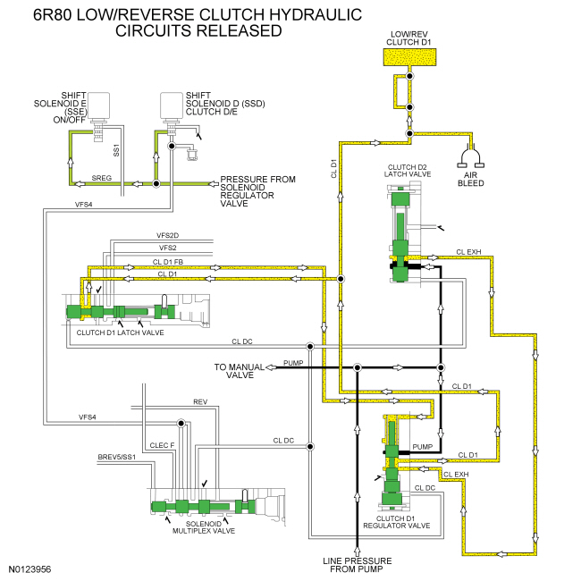
Low/Reverse Clutch (D) Hydraulic Circuits
To apply the low/reverse clutch (D), the manual valve can be in any position. Line pressure is supplied to the D1 regulator and latch valves by the pump through the PUMP circuit.
SSD provides regulated solenoid pressure from the SREG circuit to the solenoid multiplex valve through the VFS4 circuit where it is directed to the D1 regulator and latch valves through the CL DC circuit to position the valves to apply the low/reverse clutch (D). As the low/reverse clutch (D) is applied, SSD increases pressure to the D1 clutch regulator and latch valves.
The clutch D1 regulator valve provides regulated line pressure from the PUMP circuit to the CL D1 circuit to apply the low/reverse clutch (D).
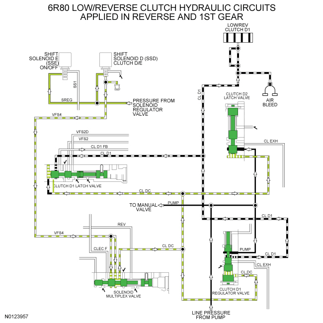
To release the low/reverse clutch (D), the manual valve can be in the DRIVE, 3 or 2 position. SSD lowers pressure to the VFS4 circuit which lowers pressure in the CL DC circuit to position the D clutch regulator and latch valves to lower pressure in the CL D1 circuit and release the low/reverse clutch (D).
When the low/reverse clutch (D) is released, the clutch D2 latch valve directs line pressure regulated to approximately 21 kPa (3 psi) to the CL EXH circuit which fills the volume of the unused clutches and circuits.
When the low/reverse clutch (D) is released, the CL EXH circuit supplies the D1 regulator valve which fills the CL D1 circuit and the low/reverse (D) clutch.
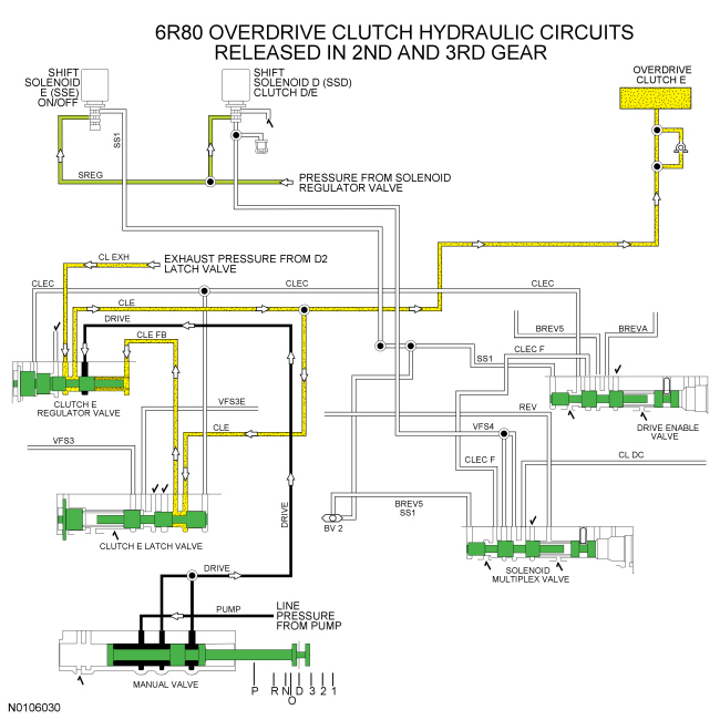
Overdrive Clutch (E) Hydraulic Circuits
To apply the overdrive clutch (E), the manual valve must be in the DRIVE position. Line pressure is supplied to the clutch E regulator valve.
SSD provides regulated solenoid pressure from the SREG circuit to the solenoid multiplex valve through the VFS4 circuit. SSE supplies pressure to the solenoid multiplex valve and the drive enable valve to position the valves to direct pressure from the VFS4 circuit to the CLEC F and CLEC circuits to position the clutch E regulator and latch valves to apply the overdrive clutch (E). As the overdrive clutch (E) is applied, SSD increases pressure to the clutch E regulator and latch valve.
The clutch E regulator valve provides regulated line pressure from the DRIVE circuit to the CLE circuit to apply the overdrive clutch (E).
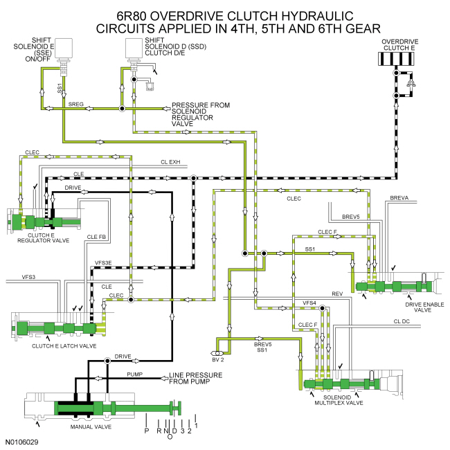
To release the overdrive clutch (E), the manual valve can be in any position. SSD lowers pressure to the VFS4 circuit which lowers pressure in the CLEC and CLEC F circuits and releases the overdrive clutch (E). SSE blocks SREG pressure to the solenoid multiplex valve and the drive enable valve to allow SSD to control low/reverse clutch (D) operation.
When the overdrive clutch (E) is released, the clutch E regulator valve directs exhaust circuit pressure from the CL EXH circuit to the CL E circuit to fill the circuit and the clutch with fluid at low pressure, approximately 21 kPa (3 psi).