b Solenoid is On when vehicle is above 3 mph.
CB = Clutch brake
NC = Normally closed
NH = Normally high
NL = Normally low
The following are brief descriptions of the sensors and actuators used to control transmission operation.
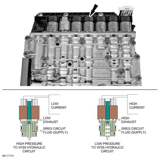
Line Pressure Control (LPC) Solenoid
The Line Pressure Control (LPC) solenoid, is a Variable Force Solenoid (VFS) that varies hydraulic pressure by actuating a hydraulic valve.
The PCM applies variable current to the LPC solenoid which varies pressure in the VFS5 hydraulic circuit to the main regulator valve. Refer to Hydraulic Circuits in this section.
The LPC solenoid uses inversely proportional operation. As the current from the PCM decreases, the pressure from the solenoid increases. As the current from the PCM increases, the pressure from the solenoid decreases. The LPC solenoid is supplied hydraulic pressure from the SREG circuit.
With zero current, the LPC solenoid fully opens the hydraulic valve which applies the maximum amount of hydraulic pressure to the main regulator valve through the VFS5 hydraulic circuit and applies maximum line pressure in the PUMP hydraulic circuit. With maximum current to the solenoid, the hydraulic valve fully closes the outlet port for minimum pressure to the VFS5 hydraulic circuit, lowering the line pressure in the PUMP hydraulic circuit.
LPC Inversely Proportional VFS
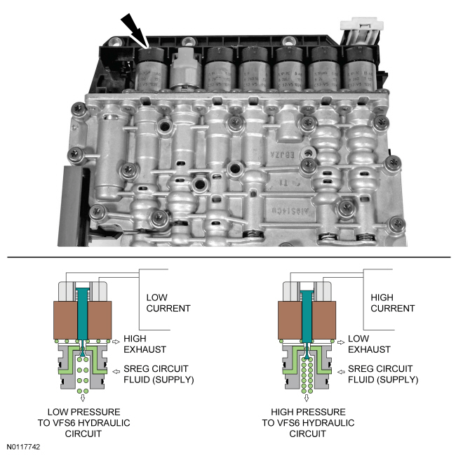
Torque Converter Clutch (TCC) Solenoid
The TCC solenoid is a VFS that varies hydraulic pressure by actuating a hydraulic valve.
The PCM applies variable current to the TCC solenoid which varies pressure in the VFS6 hydraulic circuit to the converter release regulator valve and the bypass clutch control regulator valve. Refer to Hydraulic Circuits in this section.
The TCC solenoid uses proportional operation. As the current from the PCM decreases, the pressure from the solenoid decreases. As the current from the PCM increases, the pressure from the solenoid increases. The TCC solenoid is supplied hydraulic pressure from the SREG circuit.
With zero current, the TCC solenoid fully closes the hydraulic valve which applies the minimum amount of hydraulic pressure to the converter release regulator valve and the bypass clutch control regulator valve through the VFS6 hydraulic circuit and releases the TCC . With maximum current to the solenoid, the hydraulic valve fully opens the outlet port for maximum pressure to the VFS6 hydraulic circuit to apply the TCC .
Torque Converter Clutch (TCC) Proportional VFS
Shift Solenoid A (SSA), Shift Solenoid B (SSB), Shift Solenoid C (SSC) and Shift Solenoid D (SSD)
Shift solenoids A through D are VFS that vary hydraulic pressure by actuating a hydraulic valve.
The PCM applies variable current to the shift solenoids which varies pressure in the hydraulic circuit to the regulator and latch valves of the clutch that it controls. Refer to Hydraulic Circuits in this section.
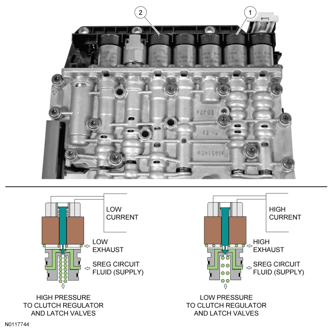
SSA and SSC use proportional operation. As the current from the PCM decreases, the pressure from the solenoid decreases. As the current from the PCM increases, the pressure from the solenoid increases. SSA and SSC are supplied hydraulic pressure from the SREG circuit.
With zero current, SSA and SSC fully close the hydraulic valves which applies zero amount of hydraulic pressure to the regulator and latch valves of the clutch that it controls and releases the clutch. With maximum current to the solenoids, the hydraulic valves fully open for maximum pressure to the regulator and latch valves to apply the clutch.
Shift Solenoid A (SSA) and Shift Solenoid C (SSC) Proportional VFS
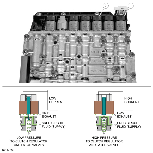
| Item | Description |
|---|---|
| 1 | Shift Solenoid A (SSA) Variable Force Solenoid (VFS) |
| 2 | Shift Solenoid C (SSC) VFS |
SSB and SSD use inverse proportional operation. As the current from the PCM decreases, the pressure from the solenoid increases. As the current from the PCM increases, the pressure from the solenoid decreases. SSB and SSD are supplied hydraulic pressure from the SREG circuit.
With zero current, SSB and SSD fully open the hydraulic valves which applies maximum hydraulic pressure to the regulator and latch valves to apply the clutch that it controls. With maximum current to the solenoids, the hydraulic valve fully closes to apply zero amount of hydraulic pressure to the regulator and latch valves of the clutch that it controls and releases the clutch.
Shift Solenoid B (SSB) and Shift Solenoid D (SSD) Inverse Proportional VFS
| Item | Description |
|---|---|
| 1 | Shift Solenoid B (SSB) Variable Force Solenoid (VFS) |
| 2 | Shift Solenoid D (SSD) VFS |
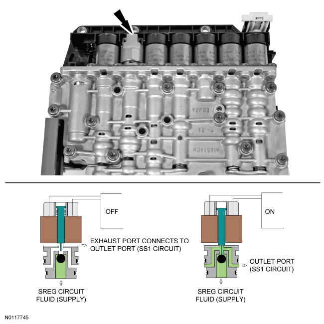
Shift Solenoid E (SSE)
SSE is an ON/OFF solenoid. When SSE is in the OFF position, SSD controls the regulator and latch valves to apply the low/reverse clutch. When SSE is in the ON position, SSD controls the regulator and latch valves to apply the overdrive (456) clutch. Refer to Hydraulic Circuits in this section.
SSE is supplied hydraulic pressure from the SREG circuit. When SSE is OFF, the solenoid supply is blocked and the outlet port (SS1 circuit) is connected to the exhaust port. When SSE is ON, the exhaust port is blocked and the solenoid supply is connected to the outlet port (SS1 circuit).
Shift Solenoid E (SSE) ON/OFF Solenoid
Turbine Shaft Speed (TSS) Sensor
The TSS sensor is a Hall-effect type sensor that provides a signal to the PCM that changes in frequency as the rotating speed of the forward (1,2,3,4) clutch cylinder varies.
The PCM compares the TSS sensor signal with the engine speed information to determine the amount of slip occurring in the torque converter.
The PCM also compares the TSS sensor signal with the OSS sensor signal to determine the gear ratio provided by the rear planetary gearset.
The PCM uses the TSS sensor signal as an input for its strategies for shifts and TCC operation. The PCM also uses the TSS sensor signal for transmission fault detection and diagnostics.
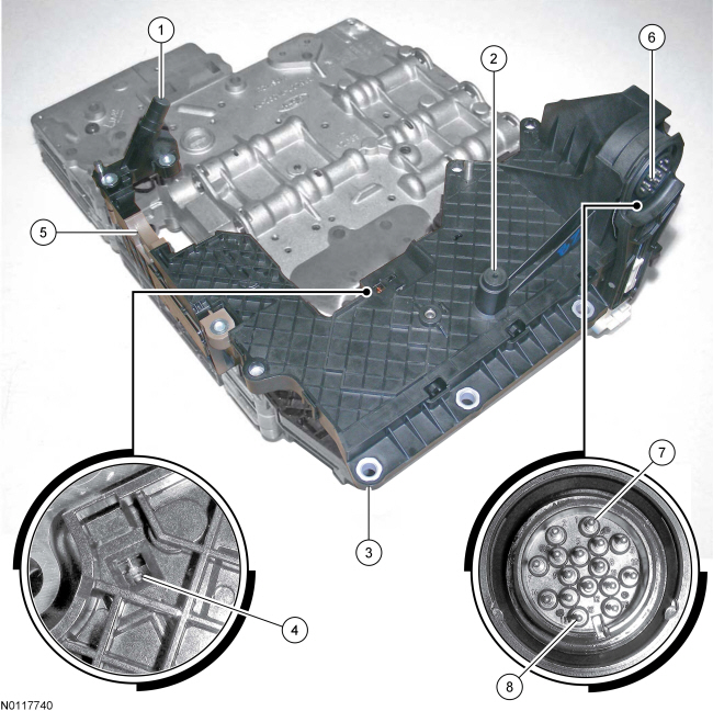
Refer to the component illustration at the beginning of this procedure for the location of the TSS sensor.
Output Shaft Speed (OSS) Sensor
The OSS sensor is a Hall-effect type sensor that provides a signal to the PCM that changes in frequency as the rotating speed of the output shaft ring gear varies.
The PCM also compares the OSS sensor signal with the TSS sensor signal to determine the gear ratio provided by the rear planetary gearset.
The PCM uses the OSS sensor signal as an input for its strategies for shifts and TCC operation. The PCM also uses the OSS sensor signal for transmission fault detection and diagnostics.
Refer to the component illustration at the beginning of this procedure for the location of the OSS sensor.
Transmission Fluid Temperature (TFT) Sensor
The TFT sensor is a temperature dependent resistor that is in contact with transmission fluid in the transmission sump area.
The PCM monitors the voltage across the TFT sensor, which changes as transmission fluid temperature varies.
The PCM uses the TFT sensor signal as an input for its strategy for shifting and TCC operation. The PCM also uses the TFT sensor signal for transmission fault detection and diagnostics.
Refer to the component illustration at the beginning of this procedure for the location of the TFT sensor.
Transmission Range (TR) Sensor
The TR sensor has a set of Hall-effect sensors that have a pattern of ON/OFF states which are dependant on the PARK, REVERSE, NEUTRAL, DRIVE, 3, 2 or 1 position of the manual valve.
The TR sensor also provides signals for the starting system and the reverse lights.
The PCM uses the TR sensor signal as an input for its strategy for shifting and TCC operation. The PCM also uses the TR sensor signal for transmission fault detection and diagnostics.
Refer to the component illustration at the beginning of this procedure for the location of the TR sensor.