Special Tool(s)
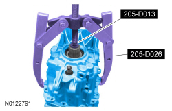
 | 2 Jaw Puller
205-D026 (D80L-1002-L) or equivalent
|
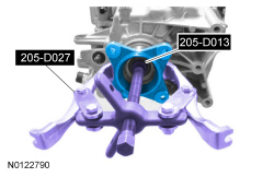
 | 2 or 3 Jaw Puller
205-D027 (D80L-1013-A) or equivalent
|
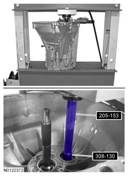
 | Handle
205-153 (T80T-4000-W)
|
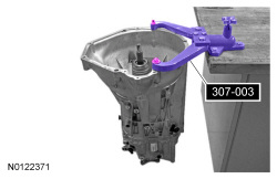
 | Holding Fixture, Transmission
307-003 (T57L-500-B)
|
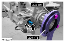
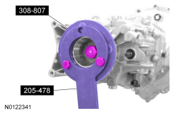
 | Holding Tool, Drive Pinion Flange
205-478
|
 | Holding Tool, Rear Flange
308-807
|
 | Installer, Shift Rail Needle Bearing
308-130 (T87T-7025-DH)
|
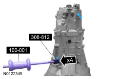
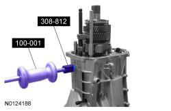
 | Remover, Detent
308-812
|
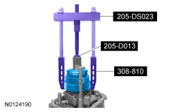
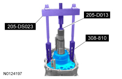
 | Push/Puller Set
205-DS023 (D80L-927-A) or equivalent
|
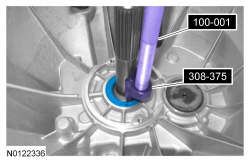
 | Remover, Input Shaft Oil Seal
308-375
|
 | Remover, Synchro Gear Pack
308-810
|
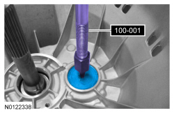
 | Slide Hammer
100-001 (T50T-100-A)
|
 | Step Plate
205-D013 (D80L-630-2) or equivalent
|
 WARNING: Do not breathe dust or use compressed air to blow dust from storage containers or friction components. Remove dust using government-approved techniques. Friction component dust may be a cancer and lung disease hazard. Exposure to potentially hazardous components may occur if dusts are created during repair of friction components, such as brake pads and clutch discs. Exposure may also cause irritation to skin, eyes and respiratory tract, and may cause allergic reactions and/or may lead to other chronic health effects. If irritation persists, seek medical attention or advice. Failure to follow these instructions may result in serious personal injury.