SECTION 308-03B: Manual Transaxle/Transmission — TR6060
| 2014 Mustang Workshop Manual
|
DISASSEMBLY
| Procedure revision date: 01/07/2013
|
Transmission
Special Tool(s)
 | 2 or 3 Jaw Puller
205-D027 (D80L-1013-A)
|
 | Holding Fixture, Transmission
307-003 (T57L-500-B)
|
 | Remover/Installer, Front Wheel Hub
204-069 (T81P-1104-C)
|
 | Removal Screw, Bearing Tube
308-092 (T84T-7025-B)
|
 | Remover/Installer, Bearing Tube
308-024 (T75L-7025-B)
|
 | Remover, Mainshaft Bearing
308-058 (T77J-7025-H)
|
 | Remover, Mainshaft Bearing
308-059 (T77J-7025-J)
|
 | Remover, Synchro Gear Pack
308-810
|
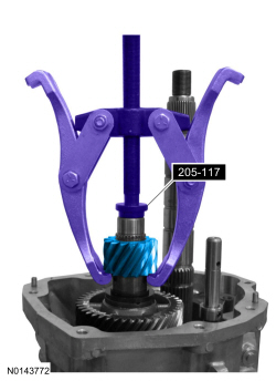
 | Step Plate
205-117 (T77F-4220-B2)
|
Disassembly
 WARNING: Do not breathe dust or use compressed air to blow dust from storage containers or friction components. Remove dust using government-approved techniques. Friction component dust may be a cancer and lung disease hazard. Exposure to potentially hazardous components may occur if dusts are created during repair of friction components, such as brake pads and clutch discs. Exposure may also cause irritation to skin, eyes and respiratory tract, and may cause allergic reactions and/or may lead to other chronic health effects. If irritation persists, seek medical attention or advice. Failure to follow these instructions may result in serious personal injury.
NOTE:
During disassembly, if any roll pins, retaining rings or bearings are removed, install new components. Install bearings and bearing cups as a set only.
NOTE:
For information on component views and base part numbers, refer to
Transmission
.
- Clean the transmission exterior with solvent and dry with compressed air. During disassembly, clean all components with solvent and dry with compressed air.
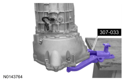
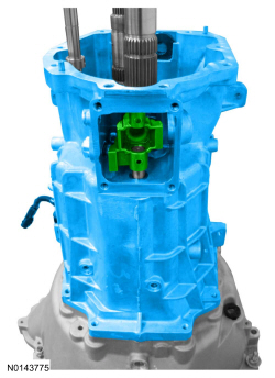
- Attach the transmission to the Transmission Holding Fixture.
- Remove the 2 clutch slave cylinder bolts, pull the clutch slave cylinder outward and release the tube from the retaining clip.
- Inspect the clutch slave cylinder for the following:
- Worn or damaged release bearing
- Rotate the release bearing while applying pressure. If the bearing rotation is rough, install a new clutch slave cylinder.
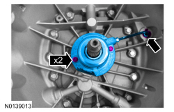
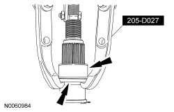
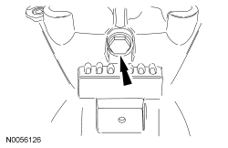
- Remove the output shaft flange nut and washer.
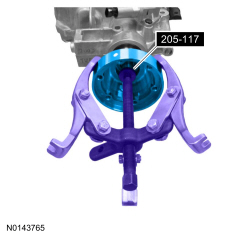
- Using a 2 or 3 Jaw Puller and Step Plate, remove the output shaft flange.
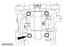
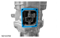
- Remove the 4 bolts and the shift detent cover.
- Remove and discard the shift detent cover gasket.
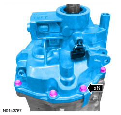
NOTE:
Note the location of the transmission identification tag.
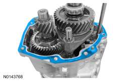
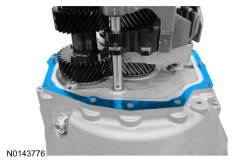
Remove the 8 bolts and carefully separate the extension housing from the transmission.
- Remove and discard the extension housing gasket.
- Using a 2 or 3 Jaw Puller, remove the bearing race and the spacer.
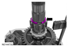
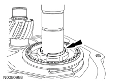
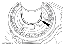
- Remove and discard the
sensor tone wheel snap ring.
- Remove the
sensor tone wheel and the ball.
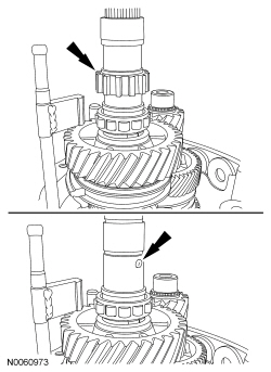
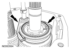
- Remove and discard the snap ring, the upper spacer, the rear output shaft roller bearing and the lower spacer.
- Inspect the rear output shaft roller bearing for wear or damage. Install a new bearing as necessary.
NOTE:
Position the gearshift lever in 3rd/4th neutral position.
Using a 5/32-inch drift and a hammer, drive the roll pins downward, then remove the reverse shift rail.
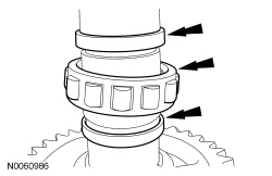
- Remove the following:
- The reverse gear snap ring.
- The reverse gear thrust washer.
- The reverse gear.
- Discard the reverse gear snap ring.
- Inspect the reverse gear for wear or damage. Install a new gear as necessary.
- Remove the reverse gear needle bearing.
- Inspect the needle bearing for wear or damage. Install a new bearing as necessary.
NOTE:
Note the position of each synchronizer ring component before removal.
Remove the reverse gear synchronizer ring assembly.
- Inspect the reverse gear synchronizer ring assembly for wear or damage. Install a new synchronizer ring assembly as necessary.
- Remove and discard the reverse synchronizer assembly snap ring.
- Remove and discard the reverse shift fork snap ring.
NOTE:
Slide the synchronizer sleeve up while removing the pressure pieces.
Remove the reverse shift fork , the reverse synchronizer sleeve and the 3 pressure pieces.
- Inspect the reverse shift fork and shift fork pads for wear or damage. Install new components as necessary.
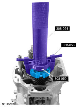
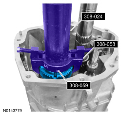
- Using the Bearing Tube Removal Screw, Bearing Tube Remover/Installer and the Mainshaft Bearing Removers, remove the reverse synchronizer hub.
- Inspect the reverse synchronizer assembly for the following:
- Check for worn, nicked or broken teeth. Install a new reverse synchronizer assembly as necessary.
- Check pressure pieces for wear or distortion. Check the pressure piece springs for distortion. Install a new reverse synchronizer assembly as necessary.
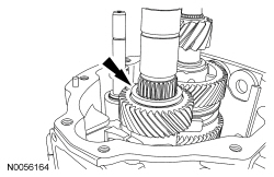
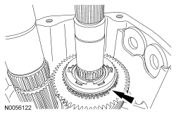
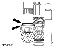
- Remove the 5th driven gear split ring and retainer.
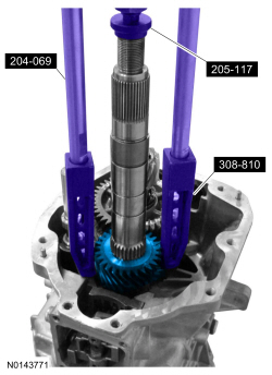
- Using the Front Wheel Hub Remover/Installer, Step Plate and the Synchro Gear Pack Remover, remove the 5th driven gear.
- Inspect the 5th driven gear for wear or damage. Install a new gear as necessary.
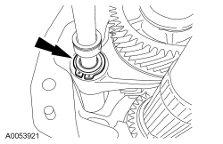
- Remove the 5th/6th shift fork snap ring.
- Remove the reverse drive gear snap ring.
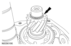
- Using a 2 or 3 Jaw Puller and Step Plate, remove the reverse drive gear.
- Inspect the reverse drive gear for wear or damage. Install a new gear as necessary.
- Remove the following:
- The 5th drive gear snap ring.
- The 5th drive gear thrust washer.
- The 5th drive gear.
- Inspect the 5th drive gear for wear or damage. Install a new gear as necessary.
- Remove the 5th gear needle bearing and spacer.
- Inspect the needle bearing for wear or damage. Install a new bearing as necessary.
NOTE:
Note the position of each synchronizer ring component before removal.
Remove the 5th gear synchronizer ring assembly.
- Inspect the 5th gear synchronizer ring assembly for wear or damage. Install a new synchronizer ring assembly as necessary.
- Remove the snap ring.
NOTE:
Slide the synchronizer sleeve up while removing the pressure pieces.
Remove the 5th/6th gear shift fork , the 5th/6th gear synchronizer sleeve and the 3 pressure pieces.
- Inspect the 5th/6th gear shift fork and shift fork pads for wear or damage. Install new components as necessary.
- Using the Bearing Tube Removal Screw, Bearing Tube Remover/Installer and the Mainshaft Bearing Removers, remove the 5th/6th gear synchronizer hub.
- Inspect the 5th/6th gear synchronizer assembly for the following:
- Check for worn, nicked or broken teeth. Install a new 5th/6th gear synchronizer assembly as necessary.
- Check the pressure pieces for wear or distortion. Check the pressure piece springs for distortion. Install a new 5th/6th gear synchronizer assembly as necessary.
NOTE:
Note the position of each synchronizer ring component before removal.
Remove the 6th gear synchronizer ring assembly.
- Inspect the 6th gear synchronizer ring assembly for wear or damage. Install a new synchronizer ring assembly as necessary.
- Remove 6th gear and needle bearing.
- Inspect the 6th gear for wear or damage. Install a new gear as necessary.
- Inspect the needle bearing for wear or damage. Install a new bearing as necessary.
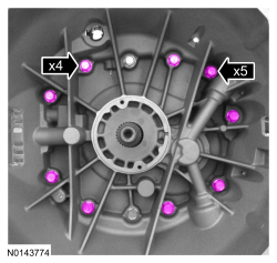
- Remove 9 of the transmission main case-to-clutch housing bolts.
NOTE:
Rotate the transmission to a vertical position.
Remove the 2 shift lever guide bolts.
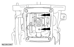
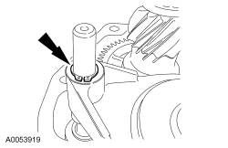
- Remove the shift lever detent plug, spring and detent.
- Remove the 2 remaining transmission main case-to-clutch housing bolts, then remove the transmission case and the front offset lever.
- Slide the transmission case upward, off the output shaft and shift rails. Hold the offset lever against the guide plate.
- Remove the transmission main case-to-clutch housing gasket.
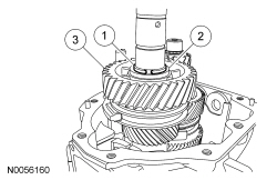
- Remove the 6th gear needle bearing spacer and thrust washer.
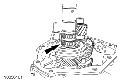
- Rotate the 5th/6th and reverse shift levers from the shift interlock plate, then remove the 5th/6th and reverse shift rail assembly.
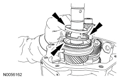
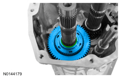
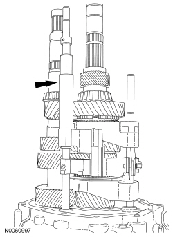
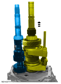
- Lift up the output shaft and shift rail assembly, then remove the countershaft.
- Remove the output shaft and shift rail as an assembly.
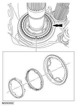
NOTE:
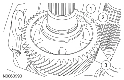
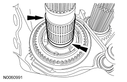
Note the position of each synchronizer ring component before removal.
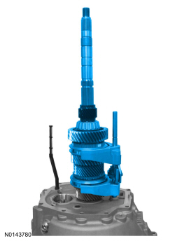
Remove the cylindrical roller bearing, the axial thrust bearing, the 4th gear synchronizer ring assembly and the input shaft.
- Inspect the input shaft for wear or damage. Install a new input shaft as necessary.
- Inspect the axial thrust and cylindrical roller bearings for wear or damage. Install new bearings as necessary.
- Check the 4th gear synchronizer ring assembly for wear or damage. Install a new synchronizer ring assembly as necessary.
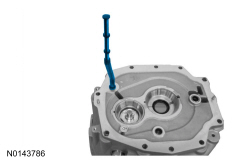
- Remove the oil pump pickup tube.
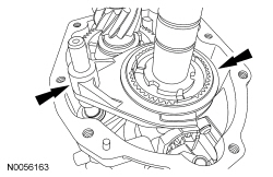
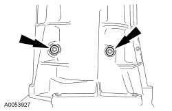
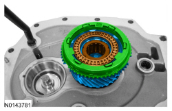
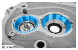
- Remove the countershaft and input shaft bearing cups and the shims.
- Inspect the cups for wear or damage. Install new cups and bearings as necessary.
- Inspect the cup bores for wear, scratches or grooves.
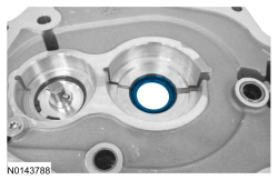
- Remove and discard the input shaft seal.
- Inspect the clutch housing for cracks. Clean and check the sealing surface for nicks or scratches.
- If the clutch housing is cracked, install a new housing.