
FLU77-4 or equivalent


NUD105-R025D or equivalent
SECTION 413-13: Parking Aid
| 2014 Mustang Workshop Manual
|
DIAGNOSIS AND TESTING
| Procedure revision date: 01/07/2013
|
| Fluke 77-IV Digital Multimeter
FLU77-4 or equivalent |
| Vehicle Communication Module (VCM) and Integrated Diagnostic System (IDS) software with appropriate hardware, or equivalent scan tool
|
| Flex Probe Kit
NUD105-R025D or equivalent |
Principles of Operation
The parking aid sensors detect objects approximately 152 cm (60 in) from the rear of the vehicle, 50 cm (20 in) from the rear side of the vehicle, and 30 cm (12 in) above the ground. The Parking Aid Module (PAM) calculates the distance to an object within the 170 degree semicircular area around the rear of the vehicle.
A variable-rate warning tone is generated from a speaker attached to the PAM . The speaker increases its warning tone rate as the vehicle gets closer to an obstacle. When an object is detected within 30 cm (12 in) of the sensors, the warning tone becomes continuous. When the PAM sounds the parking aid tone, it sends a volume cutback enabled message over the High Speed Controller Area Network (HS-CAN) to the Instrument Panel Cluster (IPC). The IPC sends a message over the Medium Speed Controller Area Network (MS-CAN) to the Audio Control Module (ACM). When the ACM receives the message, it reduces the speaker output so the parking aid tone can be heard.
The parking aid system is enabled when the ignition switch is in the RUN position and the transmission in reverse. The parking aid system is disabled if a fault is detected in 1 of the 4 sensors, the parking aid speaker, or the PAM . This is indicated by a parking aid disabled warning message in the message center.
The parking aid system is enabled and disabled through the message center, located in the Instrument Panel Cluster (IPC).
If a MyKey® restricted key is in the ignition cylinder, the parking aid menu is not available in the message center and cannot be deactivated.
The PAM communicates on the HS-CAN and can be diagnosed with a scan tool. The PAM communicates with the scan tool, the Body Control Module (BCM), and the IPC .
Inspection and Verification
Visual Inspection Chart
| Electrical |
|---|
|
NOTE: Make sure to use the latest scan tool software release.
If the cause is not visually evident, connect the scan tool to the Data Link Connector (DLC).NOTE: The Vehicle Communication Module (VCM) LED prove-out confirms power and ground from the DLC are provided to the VCM .
If the scan tool does not communicate with the vehicle:NOTE: The ignition must be OFF to carry out the Remote Function Actuator (RFA) module self-test.
Carry out the self-test diagnostics for the RFA module and Parking Aid Module (PAM).PAM PID Chart
| PID | Description |
|---|---|
| LRI_DIST | Left rear inner parking aid sensor distance |
| LRO_DIST | Left rear outer parking aid sensor distance |
| RRI_DIST | Right rear inner parking aid sensor distance |
| RRO_DIST | Right rear outer parking aid sensor distance |
| TRANSGR | Transmission gear position |
DTC Charts
NOTE: Refer to Description and Operation, Intelligent Access (IA) with Push Button Start in Section 419-01B to review the procedures for achieving the various ignition states (ignition in accessory, on, start, off) on vehicles with this feature.
Parking Aid Module (PAM) DTC Chart
| DTC | Description | Action |
|---|---|---|
| B1B44:12 | Right Rear Outer Sensor: Circuit Short To Battery | GO to Pinpoint Test C . |
| B1B44:14 | Right Rear Outer Sensor: Circuit Short To Ground Or Open | GO to Pinpoint Test B . |
| B1B44:96 | Right Rear Outer Sensor: Component Internal Failure | GO to Pinpoint Test D . |
| B1B46:12 | Right Rear Inner Sensor: Circuit Short To Battery | GO to Pinpoint Test C . |
| B1B46:14 | Right Rear Inner Sensor: Circuit Short To Ground Or Open | GO to Pinpoint Test B . |
| B1B46:96 | Right Rear Inner Sensor: Component Internal Failure | GO to Pinpoint Test D . |
| B1B48:12 | Left Rear Outer Sensor: Circuit Short To Battery | GO to Pinpoint Test C . |
| B1B48:14 | Left Rear Outer Sensor: Circuit Short To Ground Or Open | GO to Pinpoint Test B . |
| B1B48:96 | Left Rear Outer Sensor: Component Internal Failure | GO to Pinpoint Test D . |
| B1B50:12 | Left Rear Inner Sensor: Circuit Short To Battery | GO to Pinpoint Test C . |
| B1B50:14 | Left Rear Inner Sensor: Circuit Short To Ground Or Open | GO to Pinpoint Test B . |
| B1B50:96 | Left Rear Inner Sensor: Component Internal Failure | GO to Pinpoint Test D . |
| B1B52:12 | Rear Sounder-Park Aid: Circuit Short To Battery | GO to Pinpoint Test F . |
| B1B52:14 | Rear Sounder-Park Aid: Circuit Short To Ground Or Open | GO to Pinpoint Test F . |
| B1B58:11 | Rear Sensors Power Circuit: Circuit Short To Ground | GO to Pinpoint Test E . |
| P1603:55 | EEPROM Malfunction: Not Configured | PROGRAM the Parking Aid Module (PAM). REFER to Programmable Module Installation (PMI) in Section 418-01 . |
| U2024:41 | Control Module Cal-Config Data: General Checksum Failure | CLEAR the DTCs. REPEAT the PAM self-test. If DTC U2024:41 is retrieved again, INSTALL a new PAM . REFER to Parking Aid Module (PAM) in this section. CLEAR all DTCs. REPEAT the self-test. |
Symptom Chart
| Condition | Possible Sources | Action |
|---|---|---|
|
|
|
|
| |
|
|
|
|
| |
|
| |
|
|
|
|
|
|
Pinpoint Tests
Pinpoint Test A: The Parking Aid Is Inoperative
The parking aid system is enabled when the ignition switch is in the RUN position and the reverse gear is selected. The Parking Aid Module (PAM) receives reverse gear input from the PCM through the High Speed Controller Area Network (HS-CAN). A reference voltage and signal return is supplied to the parking aid sensors from the PAM . The PAM receives an input signal from each individual parking aid sensor. The system can be disabled through the message center in the Instrument Panel Cluster (IPC).
NOTE: If a MyKey® restricted key is in the ignition cylinder, the parking aid menu is not available in the message center and cannot be deactivated.
This pinpoint test is intended to diagnose the following:
| Test Step | Result / Action to Take |
|---|---|
| A1 CHECK THE DTCs FROM THE PAM SELF-TEST | |
| Yes
REFER to DTC Charts in this section. No GO to A2 . |
| A2 CHECK THE MESSAGE CENTER FOR CORRECT OPERATION | |
| Yes
GO to A3 . No REFER to Section 413-01 . |
| A3 CHECK FOR CORRECT REVERSE GEAR INPUT | |
| Yes
GO to A4 . No REFER to Section 307-01 . |
| A4 CHECK FOR CORRECT PAM OPERATION | |
| Yes
INSTALL a new PAM . REFER to Parking Aid Module (PAM) in this section. TEST the system for normal operation. No The system is operating correctly at this time. The concern may have been caused by a loose or corroded connector. |
Pinpoint Test B: DTC B1B44:14, B1B46:14, B1B48:14 Or B1B50:14
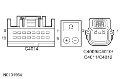
Refer to Wiring Diagrams Cell 131 , Parking Aid for schematic and connector information.
The Parking Aid Module (PAM) supplies a reference voltage and signal return to the parking aid sensors. A fault condition occurs when the PAM detects an open in the parking aid sensor circuits or the parking aid sensor input signal is open or shorted to ground.
| DTC Description | Fault Trigger Conditions |
|---|---|
| A continuous and on-demand DTC that sets when any of the right rear outer parking aid sensor circuits are open or the sensor signal line is shorted to ground. |
| A continuous and on-demand DTC that sets when any of the right rear inner parking aid sensor circuits are open or the sensor signal line is shorted to ground. |
| A continuous and on-demand DTC that sets when any of the left rear outer parking aid sensor circuits are open or the sensor signal line is shorted to ground. |
| A continuous and on-demand DTC that sets when any of the left rear inner parking aid sensor circuits are open or the sensor signal line is shorted to ground. |
This pinpoint test is intended to diagnose the following:
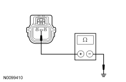
NOTICE: Use the correct probe adapter(s) when making measurements. Failure to use the correct probe adapter(s) may damage the connector.
| Test Step | Result / Action to Take | |||||||||||||||||||||||||||||||||||||||||||||||||||||||||||||||||
|---|---|---|---|---|---|---|---|---|---|---|---|---|---|---|---|---|---|---|---|---|---|---|---|---|---|---|---|---|---|---|---|---|---|---|---|---|---|---|---|---|---|---|---|---|---|---|---|---|---|---|---|---|---|---|---|---|---|---|---|---|---|---|---|---|---|---|
| B1 RETRIEVE THE DTCs FROM THE PAM SELF-TEST | ||||||||||||||||||||||||||||||||||||||||||||||||||||||||||||||||||
| Yes
GO to B2 . No For DTC B1B44:14, B1B46:14, B1B48:14 or B1B50:14, GO to B3 . For all other DTCs, REFER to DTC Charts in this section. | |||||||||||||||||||||||||||||||||||||||||||||||||||||||||||||||||
| B2 CHECK THE BUMPER WIRING HARNESS | ||||||||||||||||||||||||||||||||||||||||||||||||||||||||||||||||||
| Yes
GO to B3 . No REPAIR or INSTALL a new bumper wiring harness. CLEAR the DTCs. TEST the system for normal operation. | |||||||||||||||||||||||||||||||||||||||||||||||||||||||||||||||||
| B3 CHECK THE SENSOR CIRCUITRY FOR OPENS | ||||||||||||||||||||||||||||||||||||||||||||||||||||||||||||||||||
 | Yes
GO to B4 . No REPAIR the circuit in question. CLEAR the DTCs. TEST the system for normal operation. | |||||||||||||||||||||||||||||||||||||||||||||||||||||||||||||||||
| B4 CHECK THE SENSOR CIRCUITRY FOR SHORTS TO GROUND | ||||||||||||||||||||||||||||||||||||||||||||||||||||||||||||||||||
 | Yes
If all of the parking aid sensors recorded DTCs, GO to B5 . If one or more (but not all) parking aid sensor(s) recorded DTCs, INSTALL a new sensor(s) for the one(s) in question. REFER to Parking Aid Sensor in this section. CLEAR the DTCs. TEST the system for normal operation. No REPAIR the circuit in question. CLEAR the DTCs. TEST the system for normal operation. | |||||||||||||||||||||||||||||||||||||||||||||||||||||||||||||||||
| B5 CHECK FOR CORRECT PAM OPERATION | ||||||||||||||||||||||||||||||||||||||||||||||||||||||||||||||||||
| Yes
INSTALL a new PAM . REFER to Parking Aid Module (PAM) in this section. TEST the system for normal operation. No The system is operating correctly at this time. The concern may have been caused by a loose or corroded connector. CLEAR the DTCs. REPEAT the self-test. |
Pinpoint Test C: DTCs B1B44:12, B1B46:12, B1B48:12 and B1B50:12
Refer to Wiring Diagrams Cell 131 , Parking Aid for schematic and connector information.
The Parking Aid Module (PAM) supplies a reference voltage and signal return to the parking aid sensors. A fault condition occurs when the PAM detects a short to voltage on the parking aid sensor signal circuit.
| DTC Description | Fault Trigger Conditions |
|---|---|
| A continuous and on-demand DTC that sets when the right rear outer parking aid sensor signal line is shorted to battery voltage. |
| A continuous and on-demand DTC that sets when the right rear inner parking aid sensor signal line is shorted to battery voltage. |
| A continuous and on-demand DTC that sets when the left rear outer parking aid sensor signal line is shorted to battery voltage. |
| A continuous and on-demand DTC that sets when the left rear inner parking aid sensor signal line is shorted to battery voltage. |
This pinpoint test is intended to diagnose the following:
NOTICE: Use the correct probe adapter(s) when making measurements. Failure to use the correct probe adapter(s) may damage the connector.
| Test Step | Result / Action to Take | ||||||||||||||||||||
|---|---|---|---|---|---|---|---|---|---|---|---|---|---|---|---|---|---|---|---|---|---|
| C1 RETRIEVE THE DTCs FROM THE PAM SELF-TEST | |||||||||||||||||||||
| Yes
GO to C2 . No For DTCs B1B44:12, B1B46:12, B1B48:12 and B1B50:12, GO to C3 . For all other DTCs, REFER to DTC Charts in this section. | ||||||||||||||||||||
| C2 CHECK THE BUMPER WIRING HARNESS | |||||||||||||||||||||
| Yes
GO to C3 . No REPAIR or INSTALL a new bumper wiring harness. CLEAR the DTCs. REPEAT the self-test. | ||||||||||||||||||||
| C3 CHECK THE SENSOR CIRCUITRY FOR SHORTS TO VOLTAGE | |||||||||||||||||||||
 | Yes
REPAIR the circuit in question. CLEAR the DTCs. TEST the system for normal operation. No GO to C4 . | ||||||||||||||||||||
| C4 CHECK THE PARKING AID SENSOR CIRCUITRY FOR A SHORT TOGETHER | |||||||||||||||||||||
 | Yes
If all sensor DTCs are set, GO to C5 . If one or more parking aid sensor(s) recorded DTCs, INSTALL a new sensor(s) for the one in question. REFER to Parking Aid Sensor in this section. CLEAR the DTCs. TEST the system for normal operation. No REPAIR the circuits in question. CLEAR the DTCs. TEST the system for normal operation. | ||||||||||||||||||||
| C5 CHECK FOR CORRECT PAM OPERATION | |||||||||||||||||||||
| Yes
INSTALL a new PAM . REFER to Parking Aid Module (PAM) in this section. TEST the system for normal operation. No The system is operating correctly at this time. The concern may have been caused by a loose or corroded connector. CLEAR the DTCs. REPEAT the self-test. |
Pinpoint Test D: DTCs B1B44:96, B1B46:96, B1B48:96 and B1B50:96
The Parking Aid Module (PAM) calculates the distance to an object using 4 ultrasonic sensors mounted in the rear bumper. The parking aid sensors can detect obstructions in the path behind the vehicle.
The attenuation time for the rear parking aid sensors is the time required for a sensor to detect the distance to an object expressed in milliseconds (ms). A fault condition occurs when the signal or the attenuation time is out of normal range.
| DTC Description | Fault Trigger Conditions |
|---|---|
| A continuous and on-demand DTC that sets when the right rear outer parking aid sensor has internally failed or has an incorrect attenuation time. |
| A continuous and on-demand DTC that sets when the right rear inner parking aid sensor has internally failed or has an incorrect attenuation time. |
| A continuous and on-demand DTC that sets when the left rear outer parking aid sensor has internally failed or has an incorrect attenuation time. |
| A continuous and on-demand DTC that sets when the left rear inner parking aid sensor has internally failed or has an incorrect attenuation time. |
This pinpoint test is intended to diagnose the following:
| Test Step | Result / Action to Take |
|---|---|
| D1 CHECK THE DTCs FROM THE PAM SELF-TEST | |
| Yes
DIAGNOSE the other DTCs first. REFER to DTC Charts in this section. No GO to D2 . |
| D2 CHECK THE PARKING AID SENSOR OPERATION | |
NOTE: Make sure the area around the vehicle is clear of anything that can activate the parking aid system. | Yes
The system is operating correctly at this time. The concern may have been caused by a dirty or blocked parking aid sensor. CLEAR the DTCs. TEST the system for normal operation. No GO to D3 . |
| D3 CHECK THE PARKING AID SENSOR DISTANCE PIDs | |
| Yes
GO to D5 . No GO to D4 . |
| D4 CHECK THE PARKING AID SENSORS | |
| Yes
GO to D5 . No The cause of the concern was an inoperative parking aid sensor. The system is now operating correctly. |
| D5 CHECK FOR CORRECT PAM OPERATION | |
| Yes
INSTALL a new PAM . REFER to Parking Aid Module (PAM) in this section. TEST the system for normal operation. No The system is operating correctly at this time. The concern may have been caused by a loose or corroded connector. CLEAR the DTCs. REPEAT the self-test. |
Pinpoint Test E: DTC B1B58:11
Refer to Wiring Diagrams Cell 131 , Parking Aid for schematic and connector information.
The Parking Aid Module (PAM) supplies a reference voltage and signal return to the parking aid sensors. A fault condition occurs when the PAM detects a short to ground or signal return circuit on the parking aid sensor voltage supply circuit.
This pinpoint test is intended to diagnose the following:
NOTICE: Use the correct probe adapter(s) when making measurements. Failure to use the correct probe adapter(s) may damage the connector.
| Test Step | Result / Action to Take |
|---|---|
| E1 CHECK THE BUMPER WIRING HARNESS | |
| Yes
GO to E2 . No REPAIR or INSTALL a new bumper wiring harness. CLEAR the DTCs. TEST the system for normal operation. |
| E2 CHECK THE LH OUTER PARKING AID SENSOR FOR AN INTERNAL SHORT | |
| Yes
GO to E3 . No INSTALL a new LH outer parking aid sensor. REFER to Parking Aid Sensor in this section. CLEAR the DTCs. TEST the system for normal operation. |
| E3 CHECK THE RH OUTER PARKING AID SENSOR FOR AN INTERNAL SHORT | |
| Yes
GO to E4 . No INSTALL a new RH outer parking aid sensor. REFER to Parking Aid Sensor in this section. CLEAR the DTCs. TEST the system for normal operation. |
| E4 CHECK THE LH INNER PARKING AID SENSOR FOR AN INTERNAL SHORT | |
| Yes
GO to E5 . No INSTALL a new LH inner parking aid sensor. REFER to Parking Aid Sensor in this section. CLEAR the DTCs. TEST the system for normal operation. |
| E5 CHECK THE RH INNER PARKING AID SENSOR FOR AN INTERNAL SHORT | |
| Yes
GO to E6 . No INSTALL a new RH inner parking aid sensor. REFER to Parking Aid Sensor in this section. CLEAR the DTCs. TEST the system for normal operation. |
| E6 CHECK THE PARKING AID SENSOR VOLTAGE SUPPLY CIRCUIT FOR A SHORT TO GROUND | |
 | Yes
GO to E7 . No REPAIR the circuit. CLEAR the DTCs. TEST the system for normal operation. |
| E7 CHECK THE PARKING AID SENSOR VOLTAGE SUPPLY CIRCUIT AND GROUND CIRCUIT FOR A SHORT TOGETHER | |
 | Yes
GO to E8 . No REPAIR the circuit in question. CLEAR the DTCs. TEST the system for normal operation. |
| E8 CHECK FOR CORRECT PAM OPERATION | |
| Yes
INSTALL a new PAM . REFER to Parking Aid Module (PAM) in this section. TEST the system for normal operation. No The system is operating correctly at this time. The concern may have been caused by a loose or corroded connector. CLEAR the DTCs. REPEAT the self-test. |
Pinpoint Test F: DTCs B1B52:12 and B1B52:14
Refer to Wiring Diagrams Cell 131 , Parking Aid for schematic and connector information.
When the parking aid sensors detect obstructions in the path behind the vehicle, a variable rate warning tone is generated from the parking aid speaker. The parking aid speaker increases the warning tone rate as the vehicle gets closer to an obstacle. A fault condition occurs when the Parking Aid Module (PAM) detects an open, short to ground or short to voltage on the parking aid speaker circuits.
This pinpoint test is intended to diagnose the following:
NOTICE: Use the correct probe adapter(s) when making measurements. Failure to use the correct probe adapter(s) may damage the connector.
| Test Step | Result / Action to Take |
|---|---|
| F1 CHECK THE RECORDED DTCs FROM THE PAM SELF-TEST | |
| Yes
DIAGNOSE other DTCs first. REFER to DTC Charts in this section. No GO to F2 . |
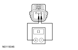
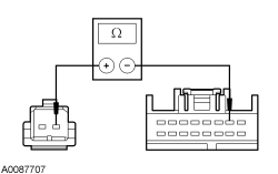
| F2 MEASURE THE PARKING AID SPEAKER RESISTANCE | |
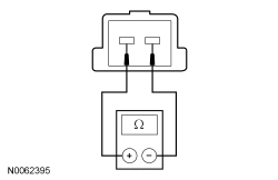 | Yes
For DTC B1B52:14, GO to F3 . For DTC B1B52:12, GO to F7 . No INSTALL a new parking aid speaker. REFER to Parking Aid Speaker in this section. CLEAR the DTCs. TEST the system for normal operation. |
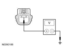
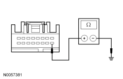
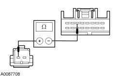
| F3 CHECK THE PARKING AID SPEAKER (+) CIRCUIT FOR A SHORT TO GROUND | |
 | Yes
GO to F5 . No GO to F4 . |
| F4 CHECK THE PARKING AID SPEAKER (+) CIRCUIT FOR A SHORT TO GROUND WITH THE PARKING AID SPEAKER DISCONNECTED | |
| Yes
REPAIR circuit RMP09 (BU/GN). CLEAR the DTCs. TEST the system for normal operation. No REPAIR circuit VMP03 (VT/GN). CLEAR the DTCs. TEST the system for normal operation. |
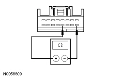
| F5 CHECK THE PARKING AID SPEAKER (+) CIRCUIT FOR AN OPEN | |
 | Yes
GO to F6 . No REPAIR the circuit. CLEAR the DTCs. TEST the system for normal operation. |
| F6 CHECK THE PARKING AID SPEAKER (-) CIRCUIT FOR AN OPEN | |
 | Yes
GO to F8 . No REPAIR the circuit. CLEAR the DTCs. TEST the system for normal operation. |
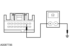
| F7 CHECK THE PARKING AID SPEAKER CIRCUITRY FOR SHORTS TO VOLTAGE | |
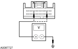 | Yes
REPAIR the circuit in question. CLEAR the DTCs. TEST the system for normal operation. No GO to F8 . |
| F8 CHECK FOR CORRECT PAM OPERATION | |
| Yes
INSTALL a new PAM . REFER to Parking Aid Module (PAM) in this section. CLEAR the DTCs. TEST the system for normal operation. No The system is operating correctly at this time. The concern may have been caused by a loose or corroded connector. CLEAR the DTCs. REPEAT the self-test. |