
FLU77-4 or equivalent


NUD105-R025D or equivalent
SECTION 417-02: Interior Lighting
| 2014 Mustang Workshop Manual
|
DIAGNOSIS AND TESTING
| Procedure revision date: 01/07/2013
|
| Fluke 77-IV Digital Multimeter
FLU77-4 or equivalent |
| Vehicle Communication Module (VCM) and Integrated Diagnostic System (IDS) software with appropriate hardware, or equivalent scan tool
|
| Flex Probe Kit
NUD105-R025D or equivalent |
Principles of Operation
The Smart Junction Box (SJB) supplies voltage to the interior lighting system. The interior lighting system illuminates the courtesy lamp to enhance visibility of the interior. When a vehicle door is ajar and the vehicle speed is less than 15 km/h (9 mph), or the instrument panel dimmer switch is in the DOME LAMP position, the SJB provides voltage to the courtesy lamp circuit. The SJB controls all interior lighting functions and timing by monitoring inputs from the door ajar switches, the instrument panel dimmer switch, and vehicle speed.
The instrument panel dimmer switch receives a voltage signal from the SJB . The instrument panel dimmer switch provides variable resistance for backlighting the Instrument Panel Cluster (IPC) and a toggle on/off function for the courtesy lamp.
The Remote Keyless Entry (RKE) receiver is contained inside the SJB . When the SJB receives an unlock request from a RKE transmitter, it unlocks the doors and turns on the courtesy lamp.
Interior Lamp Arbitrator
The SJB chooses between the interior lighting, dome defeat, interior lighting delay, illuminated entry, illuminated exit and battery saver to determine which feature has precedence of activating and deactivating the interior lamps.
Ambient Lighting
The Body Control Module B (BCM-B) monitors the door courtesy lighting, courtesy lighting delay and illuminated exit requests. When a door is opened, the BCM-B turns on all 3 zones of the ambient lighting system. Zone 3 (door scuff plate LEDs) are turned off when any door is closed, or the illuminated entry request is detected by the BCM-B . The other 2 zones are turned off at the same time as the courtesy lighting by the BCM-B if the key is not activated in the ignition switch. The ambient lighting is reactivated when the ignition is placed in the accessory ON or RUN position.
The color of the LEDs always defaults to the last setting in the memory. There are 125 different color combinations that are achieved by adjusting the 3 primary (red, green and blue) colors.
Field-Effect Transistor (FET) Protection
Field-Effect Transistor (FET) is a type of transistor that when used with module software can be used to monitor and control current flow on module outputs. The FET protection strategy is used to prevent module damage in the event of excessive current flow.
The SJB utilizes an FET protective circuit strategy for many of its outputs (for example, a headlamp output circuit). Output loads (current level) are monitored for excessive current (typically short circuits) and are shut down (turns off the voltage or ground provided by the module) when a fault event is detected. A continuous DTC is stored at the fault event and a cumulative counter is started.
When the demand for the output is no longer present, the module resets the FET circuit protection to allow the circuit to function. The next time the driver requests a circuit to activate that has been shut down by a previous short ( FET protection) and the circuit remains shorted, the FET protection shuts off the circuit again and the cumulative counter advances.
When the excessive circuit load occurs often enough, the module shuts down the output until a repair procedure is carried out. Each FET protected circuit has 3 predefined levels of short circuit tolerance based on the harmful effect of each circuit fault on the FET and the ability of the FET to withstand it. A module lifetime level of fault events is established based upon the durability of the FET . If the total tolerance level is determined to be 600 fault events, the 3 predefined levels would be 200, 400 and 600 fault events.
When each tolerance level is reached, the continuous DTC that was stored on the first failure cannot be cleared by a command to clear the continuous DTCs. The module does not allow this code to be cleared or the circuit restored to normal operation until a successful self-test proves that the fault has been repaired. After the self-test has successfully completed (no on-demand DTCs present), DTC B106E and the associated continuous DTC (the DTC related to the shorted circuit) automatically clears and the circuit function returns.
When the first or second level is reached, the continuous DTC (associated with the short circuit) sets along with DTC B106E. These DTCs can be cleared using the module on-demand self-test, then the Clear DTC operation on the scan tool (if the on-demand test shows the fault corrected). The module never resets the fault event counter to zero and continues to advance the fault event counter as short circuit fault events occur.
If the number of short circuit fault events reach the third level, then DTCs B106F and B1342 set along with the associated continuous DTC. This DTC cannot be cleared and the module must be replaced.
The BCM-B utilizes a similar strategy.
The SJB FET protected output circuits for the interior lighting system is the courtesy lamp output circuit.
The BCM-B FET protected output circuits for the interior lighting system are the ambient lighting output circuits.
Inspection and Verification
Visual Inspection Chart
| Mechanical | Electrical |
|---|---|
|
|
NOTE: Make sure to use the latest scan tool release software.
If the cause is not visually evident, connect the scan tool to the Data Link Connector (DLC).NOTE: The Vehicle Communication Module (VCM) LED prove-out confirms power and ground from the DLC are provided to the VCM .
If the scan tool does not communicate with the VCM :DTC Charts
Diagnostics in this manual assume a certain skill level and knowledge of Ford-specific diagnostic practices. Refer to Diagnostic Methods in Section 100-00 for information about these practices.
Smart Junction Box (SJB) DTC Chart
| DTC | Description | Action |
|---|---|---|
| B106E | Solid State Driver Disabled Due to Short Circuit | The module has temporarily disabled an output because an excessive current draw exists (such as a short to ground). The Smart Junction Box (SJB) cannot enable the output until the cause of the short is corrected. ADDRESS all other DTCs first. After the cause of the concern is corrected, CLEAR the DTCs. REPEAT the self-test. |
| B106F | Module Disabled Due to External Fault | The module has permanently disabled an output because an excessive current draw fault (such as a short to ground) has exceeded the limits that the SJB can withstand. The cause of the excessive current draw MUST be corrected before a new SJB is installed. ADDRESS all other DTCs first. After the cause of the concern is corrected, INSTALL a new SJB . REFER to Section 419-10 . TEST the system for normal operation. |
| B1320 | Driver Door Ajar Circuit Open | GO to Pinpoint Test D . |
| B1328 | Passenger Door Ajar Circuit Open | GO to Pinpoint Test D . |
| B1331 | Decklid Ajar Rear Door Circuit Failure | GO to Pinpoint Test F . |
| B1688 | Lamp Dome Input Circuit Short to Ground | GO to Pinpoint Test D . |
| B2A35 | Interior Lighting Output Circuit Open | If the interior courtesy lamp is inoperative,
GO to Pinpoint Test C
.
If the interior courtesy lamp stays on continuously, GO to Pinpoint Test D . |
| B2A36 | Interior Lighting Output Circuit Short to Ground | GO to Pinpoint Test C . |
| B2A38 | Floor Lamp Circuit Short to Ground | DIAGNOSE all other DTCs and symptoms first. If no other DTCs or symptoms are present, INSPECT the
SJB
and C2280a for bent pins, loose or corroded connections.
If no concerns are found, INSTALL a new SJB . REFER to Section 419-10 . TEST the system for normal operation. |
| B2A39 | Puddle Lamp Output Circuit Open | If the pony projection lights are inoperative,
GO to Pinpoint Test J
.
If the pony projection lights are always on, GO to Pinpoint Test K . |
| B2A3A | Puddle Lamp Output Circuit Short to Ground | GO to Pinpoint Test J . |
| All other DTCs | — | REFER to the Diagnostic Trouble Code (DTC) Chart in Section 419-10 . |
Body Control Module B (BCM-B) DTC Chart
| DTC | Description | Action |
|---|---|---|
| B127B:11 | Ambient Lighting Zone 1 Output Red LED Circuit Short To Ground | GO to Pinpoint Test H . |
| B127B:15 | Ambient Lighting Zone 1 Output Red LED Circuit Short To Battery or Open | If the ambient lighting is inoperative,
GO to Pinpoint Test I
.
If the ambient lighting does not cycle through all colors, GO to Pinpoint Test H . |
| B127C:11 | Ambient Lighting Zone 2 Output Red LED Circuit Short To Ground | GO to Pinpoint Test H . |
| B127C:15 | Ambient Lighting Zone 2 Output Red LED Circuit Short To Battery or Open | If the ambient lighting is inoperative,
GO to Pinpoint Test I
.
If the ambient lighting does not cycle through all colors, GO to Pinpoint Test H . |
| B127D:11 | Ambient Lighting Zone 3 Output Red LED Circuit Short To Ground | GO to Pinpoint Test H . |
| B127D:15 | Ambient Lighting Zone 3 Output Red LED Circuit Short To Battery or Open | If the ambient lighting is inoperative,
GO to Pinpoint Test I
.
If the ambient lighting does not cycle through all colors, GO to Pinpoint Test H . |
| B127E:11 | Ambient Lighting Zone 1 Output Green LED Circuit Short To Ground | GO to Pinpoint Test H . |
| B127E:15 | Ambient Lighting Zone 1 Output Green LED Circuit Short To Battery or Open | If the ambient lighting is inoperative,
GO to Pinpoint Test I
.
If the ambient lighting does not cycle through all colors, GO to Pinpoint Test H . |
| B127F:11 | Ambient Lighting Zone 2 Output Green LED Circuit Short To Ground | GO to Pinpoint Test H . |
| B127F:15 | Ambient Lighting Zone 2 Output Green LED Circuit Short To Battery or Open | If the ambient lighting is inoperative,
GO to Pinpoint Test I
.
If the ambient lighting does not cycle through all colors, GO to Pinpoint Test H . |
| B1280:11 | Ambient Lighting Zone 3 Output Green LED Circuit Short To Ground | GO to Pinpoint Test H . |
| B1280:15 | Ambient Lighting Zone 3 Output Green LED Circuit Short To Battery or Open | If the ambient lighting is inoperative,
GO to Pinpoint Test I
.
If the ambient lighting does not cycle through all colors, GO to Pinpoint Test H . |
| B1281:11 | Ambient Lighting Zone 1 Output Blue LED Circuit Short To Ground | GO to Pinpoint Test H . |
| B1281:15 | Ambient Lighting Zone 1 Output Blue LED Circuit Short To Battery or Open | If the ambient lighting is inoperative,
GO to Pinpoint Test I
.
If the ambient lighting does not cycle through all colors, GO to Pinpoint Test H . |
| B1282:11 | Ambient Lighting Zone 2 Output Blue LED Circuit Short To Ground | GO to Pinpoint Test H . |
| B1282:15 | Ambient Lighting Zone 2 Output Blue LED Circuit Short To Battery or Open | If the ambient lighting is inoperative,
GO to Pinpoint Test I
.
If the ambient lighting does not cycle through all colors, GO to Pinpoint Test H . |
| B1283:11 | Ambient Lighting Zone 3 Output Blue LED Circuit Short To Ground | GO to Pinpoint Test H . |
| B1283:15 | Ambient Lighting Zone 3 Output Blue LED Circuit Short To Battery or Open | If the ambient lighting is inoperative,
GO to Pinpoint Test I
.
If the ambient lighting does not cycle through all colors, GO to Pinpoint Test H . |
| U1000:00 | Solid State Drive Protection Activated-Driver Disabled: No Sub Type Information | The module has temporarily disabled an output because an excessive current draw exists (such as a short to ground). The Body Control Module B (BCM-B) cannot enable the output until the cause of the short is corrected. ADDRESS all other DTCs first. After the cause of the concern is corrected, CLEAR the DTCs. REPEAT the self-test. |
| U3000:49 | Control Module: Internal Electronic Failure | The module has permanently disabled an output because an excessive current draw fault (such as a short to ground) has exceeded the limits that the BCM-B BCM-B can withstand. The cause of the excessive current draw MUST be corrected before a new BCM-B is installed. ADDRESS all other DTCs first. After the cause of the concern is corrected, INSTALL a new BCM-B . REFER to Section 419-10 . TEST the system for normal operation. |
| All other DTCs | — | REFER to the Diagnostic Trouble Code (DTC) Chart in Section 419-10 . |
Symptom Chart
Diagnostics in this manual assume a certain skill level and knowledge of Ford-specific diagnostic practices. Refer to Diagnostic Methods in Section 100-00 for information about these practices.
| Condition | Possible Sources | Action |
|---|---|---|
|
|
|
|
| |
|
| |
|
| |
|
| |
|
| |
|
| |
|
| |
|
| |
|
| |
|
| |
|
| |
|
|
Pinpoint Tests
Pinpoint Test A: The Courtesy Lamp Does Not Turn On With A Door Open
Refer to Wiring Diagrams Cell 89 , Interior Lamps for schematic and connector information.
Refer to Wiring Diagrams Cell 117 , Remote Keyless Entry And Alarm for schematic and connector information.
The Smart Junction Box (SJB) sends a voltage signal to the door ajar switches. When the door is closed, the voltage signal is routed to ground. When the door is opened, the signal to ground is interrupted indicating an open door to the SJB .
When any door is opened, or an unlock request from a programmed Remote Keyless Entry (RKE) transmitter is detected, the SJB provides voltage to the courtesy lamp.
This pinpoint test is intended to diagnose the following:
NOTICE: Use the correct probe adapter(s) when making measurements. Failure to use the correct probe adapter(s) may damage the connector.
| Test Step | Result / Action to Take | |||||||||
|---|---|---|---|---|---|---|---|---|---|---|
| A1 CHECK THE COURTESY LAMP OPERATION USING THE INSTRUMENT PANEL DIMMER SWITCH | ||||||||||
| Yes
GO to A2 . No GO to Pinpoint Test C . | |||||||||
| A2 CHECK THE DOOR AJAR SWITCH OPERATION | ||||||||||
| Yes
INSTALL a new door latch in question. REFER to Section 501-14 . TEST the system for normal operation. No GO to A3 . | |||||||||
| A3 CHECK THE AJAR SWITCH CIRCUIT FOR A SHORT TO GROUND | ||||||||||
 | Yes
GO to A4 . No REPAIR the circuit in question for a short to ground. TEST the system for normal operation. | |||||||||
| A4 CHECK FOR CORRECT SJB OPERATION | ||||||||||
| Yes
INSTALL a new SJB . REFER to Section 419-10 . TEST the system for normal operation. No The system is operating correctly at this time. The concern may have been caused by a loose or corroded connector. |
Pinpoint Test B: The Courtesy Lamp Is Inoperative From The Instrument Panel Dimmer Switch
Refer to Wiring Diagrams Cell 89 , Interior Lamps for schematic and connector information.
The Smart Junction Box (SJB) monitors the instrument panel dimmer switch status to determine if the courtesy lamp is requested. Based on the instrument panel dimmer switch status, the SJB supplies voltage to the courtesy lamp.
This pinpoint test is intended to diagnose the following:
NOTICE: Use the correct probe adapter(s) when making measurements. Failure to use the correct probe adapter(s) may damage the connector.
| Test Step | Result / Action to Take |
|---|---|
| B1 CHECK THE DIMMABLE BACKLIGHTING OPERATION | |
| Yes
GO to B2 . No REFER to Section 413-00 . |
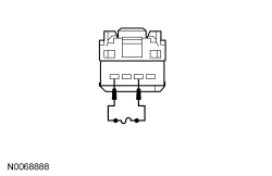
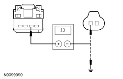
| B2 CHECK THE INSTRUMENT PANEL DIMMER SWITCH | |
 | Yes
REMOVE the jumper wire. INSTALL a new instrument panel dimmer switch. REFER to Section 413-00 . TEST the system for normal operation. No REMOVE the jumper wire. GO to B3 . |
| B3 CHECK THE DOME LAMP REQUEST INPUT CIRCUIT FOR AN OPEN | |
 | Yes
GO to B4 . No REPAIR circuit CLN28 (GN/BU) for an open. TEST the system for normal operation. |
| B4 CHECK FOR CORRECT SJB OPERATION | |
| Yes
INSTALL a new SJB . REFER to Section 419-10 . TEST the system for normal operation. No The system is operating correctly at this time. The concern may have been caused by a loose or corroded connector. |
Pinpoint Test C: The Interior Courtesy Lamp Is Inoperative
Refer to Wiring Diagrams Cell 89 , Interior Lamps for schematic and connector information.
Voltage is supplied to the courtesy lamp by the Smart Junction Box (SJB) fuse 9 (15A). Based on the input status, the SJB supplies voltage to the courtesy lamp.
| DTC Description | Fault Trigger Conditions |
|---|---|
| A continuous DTC that sets when the SJB has temporarily shut down the output driver. The module has temporarily disabled the courtesy lamp output because an excessive current draw exists (such as a short to ground). The SJB cannot enable the courtesy lamp output until the cause of the short is corrected, the DTCs have been cleared and a successful self-test is run. |
| A continuous DTC that sets when the SJB has permanently shut down the output driver. The module has permanently disabled the courtesy lamp output because an excessive current draw fault (such as a short to ground) has exceeded the limits that the SJB can withstand. The cause of the excessive current draw MUST be corrected before a new SJB is installed. |
| An on-demand DTC that sets when the SJB detects an open from the courtesy lighting output circuit. |
| A continuous and on-demand DTC that sets when the SJB detects a short to ground from the courtesy lighting output circuit. |
This pinpoint test is intended to diagnose the following:
NOTICE: Use the correct probe adapter(s) when making measurements. Failure to use the correct probe adapter(s) may damage the connector.
| Test Step | Result / Action to Take | |||||||||
|---|---|---|---|---|---|---|---|---|---|---|
| C1 CHECK THE OPERATION OF THE COURTESY LAMP FROM THE DOOR AND THE INSTRUMENT PANEL DIMMER SWITCH | ||||||||||
| Yes
VERIFY the SJB fuse 9 (15A) is OK. If OK, GO to C2 . If not OK, REFER to the Wiring Diagrams Manual to identify the possible causes of the circuit short. After the repair, if no DTCs are present, TEST the system for normal operation. If DTC B106E is present, CLEAR the DTCs and REPEAT the self-test (required to enable the courtesy lamp output driver if DTC B106E is present) . TEST the system for normal operation. If DTC B106F is present, INSTALL a new SJB . REFER to Section 419-10 . TEST the system for normal operation. No If inoperative from the door, GO to Pinpoint Test A . If inoperative from the instrument panel dimmer switch, GO to Pinpoint Test B . | |||||||||
| C2 CHECK FOR VOLTAGE TO THE INTERIOR LAMP | ||||||||||
 | Yes
GO to C3 . No GO to C4 . | |||||||||
| C3 CHECK FOR VOLTAGE TO THE INTERIOR LAMP USING THE CONNECTOR GROUND | ||||||||||
 | Yes
INSTALL a new overhead console. REFER to Section 501-12 . TEST the system for normal operation. No REPAIR circuit GD139 (BK/YE) for an open. TEST the system for normal operation. | |||||||||
| C4 BYPASS THE SJB | ||||||||||
 | Yes
REMOVE the jumper wire. GO to C5 . No REMOVE the jumper wire. REPAIR circuit VLN33 (GY/VT) for an open. CLEAR the DTCs. REPEAT the self-test. | |||||||||
| C5 CHECK FOR CORRECT SJB OPERATION | ||||||||||
| Yes
INSTALL a new SJB . REFER to Section 419-10 . TEST the system for normal operation. No The system is operating correctly at this time. The concern may have been caused by a loose or corroded connector. |
Pinpoint Test D: The Interior Courtesy Lamp Stays On Continuously
Refer to Wiring Diagrams Cell 89 , Interior Lamps for schematic and connector information.
Refer to Wiring Diagrams Cell 117 , Remote Keyless Entry And Alarm for schematic and connector information.
The Smart Junction Box (SJB) sends a voltage signal to the door ajar switches. When the door is closed, the voltage signal is routed to ground. When the door is opened, the signal to ground is interrupted indicating an open door to the SJB .
The SJB also monitors the instrument panel dimmer switch status to determine if the courtesy lamp is requested. When the instrument panel dimmer switch is rotated to the DOME LAMP position, ground is supplied to DOME LAMP request input circuit.
When the request from the instrument panel dimmer switch is detected, any door is opened, or an unlock request from a programmed Remote Keyless Entry (RKE) transmitter is detected, the SJB supplies voltage to the courtesy lamp.
| DTC Description | Fault Trigger Conditions |
|---|---|
| An on-demand DTC that sets when the SJB detects an open from the LH front door ajar input circuit. |
| An on-demand DTC that sets when the SJB detects an open from the RH front door ajar input circuit. |
| An on-demand DTC that sets when the SJB detects a short to ground from the instrument panel dimmer switch circuit. |
| An on-demand DTC that sets when the SJB detects a short to voltage from the courtesy lamp output circuit. |
This pinpoint test is intended to diagnose the following:
NOTICE: Use the correct probe adapter(s) when making measurements. Failure to use the correct probe adapter(s) may damage the connector.
| Test Step | Result / Action to Take | |||||||||
|---|---|---|---|---|---|---|---|---|---|---|
| D1 CHECK THE RECORDED DTCs FROM THE SJB SELF-TEST | ||||||||||
| Yes
For DTC B1320 or DTC B1328, GO to D2 . For DTC B1688, GO to D5 . For DTC B2A35, GO to D7 . No GO to D7 . | |||||||||
| D2 CHECK FOR VOLTAGE TO THE DOOR AJAR SWITCH | ||||||||||
 | Yes
GO to D3 . No GO to D4 . | |||||||||
| D3 CHECK FOR VOLTAGE TO THE DOOR AJAR SWITCH USING THE CONNECTOR GROUND | ||||||||||
 | Yes
INSTALL a new door latch for the ajar switch in question. REFER to Section 501-14 . CLEAR the DTCs. REPEAT the self-test. No REPAIR the ground circuit in question for an open. CLEAR the DTCs. REPEAT the self-test. | |||||||||
| D4 CHECK THE DOOR AJAR SWITCH INPUT CIRCUIT FOR AN OPEN | ||||||||||
 | Yes
GO to D8 . No REPAIR the circuit in question. CLEAR the DTCs. REPEAT the self-test. | |||||||||
| D5 CHECK THE INSTRUMENT PANEL DIMMER SWITCH | ||||||||||
NOTE: Make sure the doors are closed for correct test results. | Yes
GO to D6 . No INSTALL a new instrument panel dimmer switch. REFER to Section 413-00 . TEST the system for normal operation. | |||||||||
| D6 CHECK THE INSTRUMENT PANEL DIMMER SWITCH DOME LAMP REQUEST INPUT CIRCUIT FOR A SHORT TO GROUND | ||||||||||
 | Yes
GO to D8 . No REPAIR circuit CLN28 (GN/BU) for a short to ground. CLEAR the DTCs. REPEAT the self-test. | |||||||||
| D7 CHECK THE SJB COURTESY LAMP OUTPUT CIRCUIT FOR A SHORT TO VOLTAGE | ||||||||||
| Yes
REPAIR circuit VLN33 (GY/VT) for a short to voltage. CLEAR the DTCs. REPEAT the self-test. No GO to D8 . | |||||||||
| D8 CHECK FOR CORRECT SJB OPERATION | ||||||||||
| Yes
INSTALL a new SJB . REFER to Section 419-10 . TEST the system for normal operation. No The system is operating correctly at this time. The concern may have been caused by a loose or corroded connector. TEST the system for normal operation. |
Pinpoint Test E: One Or More Demand Lamp Is Inoperative
Refer to Wiring Diagrams Cell 89 , Interior Lamps for schematic and connector information.
The Smart Junction Box (SJB) supplies voltage to the demand lamps using the battery saver relay. The overhead console map lamp shares ground with the courtesy lamp.
This pinpoint test is intended to diagnose the following:
NOTICE: Use the correct probe adapter(s) when making measurements. Failure to use the correct probe adapter(s) may damage the connector.
| Test Step | Result / Action to Take |
|---|---|
| E1 CHECK THE COURTESY LAMP OPERATION | |
| Yes
GO to E2 . No GO to Pinpoint Test C . |
| E2 CHECK THE OPERATION OF ALL THE DEMAND LAMPS | |
| Yes
VERIFY the SJB fuse 25 (10A) is OK. If OK, GO to E5 . If not OK, REFER to the Wiring Diagrams Manual to identify the possible cause of the circuit short. No GO to E3 . |
| E3 CHECK FOR VOLTAGE TO THE DEMAND LAMP | |
    | Yes
For the overhead console, INSTALL a new overhead console. REFER to Section 501-12 . TEST the system for normal operation. For a glove compartment lamp and vanity mirror, GO to E4 . No REPAIR circuit CLN09 (YE/GN) for an open. TEST the system for normal operation. |
| E4 CHECK THE VANITY MIRROR LAMP GROUND CIRCUIT FOR AN OPEN | |
  | Yes
INSTALL a new sun visor. TEST the system for normal operation. No REPAIR circuit GD139 (BK/YE) or GD114 (BK/BU) for an open. TEST the system for normal operation. |
| E5 BYPASS THE SJB | |
 | Yes
REMOVE the jumper wire. GO to E7 . No If equipped with vanity mirror lamps, REMOVE the jumper wire. REPAIR circuit CLN09 (YE/GN) for an open. TEST the system for normal operation. If not equipped with vanity mirror lamps, LEAVE the jumper wire connected. GO to E6 . |
| E6 CHECK THE DEMAND LAMP VOLTAGE SUPPLY CIRCUIT FOR AN OPEN | |
| Yes
REMOVE the jumper wire. INSTALL a new overhead console. REFER to Section 501-12 . TEST the system for normal operation. No REMOVE the jumper wire. REPAIR circuit CLN09 (YE/GN) for an open. TEST the system for normal operation. |
| E7 CHECK FOR CORRECT SJB OPERATION | |
| Yes
INSTALL a new SJB . REFER to Section 419-10 . TEST the system for normal operation. No The system is operating correctly at this time. The concern may have been caused by a loose or corroded connector. TEST the system for normal operation. |
Pinpoint Test F: The Luggage Compartment Lamp Is Inoperative/Always On
Refer to Wiring Diagrams Cell 89 , Interior Lamps for schematic and connector information.
Power is supplied to the luggage compartment lamp from the demand lighting circuit. Ground for the luggage compartment lamp is controlled by the luggage compartment lid latch. When the luggage compartment lid is opened, a switch inside the latch closes and completes the path to ground.
This pinpoint test is intended to diagnose the following:
NOTICE: Use the correct probe adapter(s) when making measurements. Failure to use the correct probe adapter(s) may damage the connector.
NOTE: Make sure the map lamps operate correctly before continuing diagnostics.
| Test Step | Result / Action to Take |
|---|---|
| F1 CHECK THE LUGGAGE COMPARTMENT LATCH | |
| Yes
GO to F2 . No REFER to Section 501-14 . |
| F2 CHECK THE LUGGAGE COMPARTMENT AJAR PID | |
| Yes
GO to F5 . No GO to F3 . |
| F3 CHECK THE LUGGAGE COMPARTMENT AJAR SWITCH | |
 | Yes
REMOVE the jumper wire. INSTALL a new luggage compartment lid latch. REFER to Section 501-14 . TEST the system for normal operation. No REMOVE the jumper wire. GO to F4 . |
| F4 CHECK CIRCUIT CPL58 (GY/OG) FOR AN OPEN AND SHORT TO GROUND | |
 | Yes
GO to F8 . No REPAIR the circuit. CLEAR the DTCs. REPEAT the self-test. |
| F5 CHECK CIRCUIT CLN09 (YE/GN) FOR AN OPEN | |
 | Yes
GO to F6 . No REPAIR the circuit. TEST the system for normal operation. |
| F6 CHECK THE LUGGAGE COMPARTMENT LATCH | |
 | Yes
REMOVE the jumper wire. INSTALL a new luggage compartment lid latch. REFER to Section 501-14 . TEST the system for normal operation. No REMOVE the jumper wire. GO to F7 . |
| F7 CHECK CIRCUIT CLN13 (WH/BU) FOR AN OPEN AND SHORT TO GROUND | |
 | Yes
INSTALL a new luggage compartment lamp. TEST the system for normal operation. No REPAIR the circuit. TEST the system for normal operation. |
| F8 CHECK FOR CORRECT SJB OPERATION | |
| Yes
INSTALL a new SJB . REFER to Section 419-10 . TEST the system for normal operation. No The system is operating correctly at this time. The concern may have been caused by a loose or corroded connector. TEST the system for normal operation. |
Pinpoint Test G: The Battery Saver Does Not Deactivate After Time-Out
Refer to Wiring Diagrams Cell 89 , Interior Lamps for schematic and connector information.
The Smart Junction Box (SJB) controls the battery saver function. The battery saver function provides automatic shutoff of the interior lamps (courtesy and demand lamps) after 10 minutes have elapsed in order to save battery power.
This pinpoint test is intended to diagnose the following:
| Test Step | Result / Action to Take |
|---|---|
| G1 CHECK THE SJB IGNITION SWITCH PIDs | |
| Yes
GO to G2 . No REFER to Section 211-05 . |
| G2 CHECK THE DEMAND LAMP VOLTAGE SUPPLY CIRCUIT FOR A SHORT TO VOLTAGE | |
| Yes
REPAIR the circuit. TEST the system for normal operation. No GO to G3 . |
| G3 CHECK FOR CORRECT SJB OPERATION | |
| Yes
INSTALL a new SJB . REFER to Section 419-10 . TEST the system for normal operation. No The system is operating correctly at this time. The concern may have been caused by a loose or corroded connector. |
Pinpoint Test H: The Ambient Lighting Does Not Cycle Through All Color Variations (Single LED or Zone)
Refer to Wiring Diagrams Cell 89 , Interior Lamps for schematic and connector information.
The Body Control Module B (BCM-B) supplies voltage and ground to the LEDs located in the floor console cup holders, console storage bin, driver and passenger scuff plates, both door map pockets and the front and rear footwells. The message center is used to cycle through the color combinations or to turn the ambient lighting feature off. There are 3 different color (red, blue and green) LEDs housed within each LED assembly.
The BCM-B has a built-in self-test that cycles through red, green and blue colors for each zone separately. Using this test may help diagnose a single color failure.
| DTC Description | Fault Trigger Conditions |
|---|---|
| A continuous DTC that sets when the BCM-B detects a short to ground from the ambient lighting zone 1 red circuit. |
| A continuous DTC that sets when the BCM-B detects a short to ground from the ambient lighting zone 1 green circuit. |
| A continuous DTC that sets when the BCM-B detects a short to ground from the ambient lighting zone 1 blue circuit. |
| A continuous DTC that sets when the BCM-B detects a short to ground from the ambient lighting zone 2 red circuit. |
| A continuous DTC that sets when the BCM-B detects a short to ground from the ambient lighting zone 2 green circuit. |
| A continuous DTC that sets when the BCM-B detects a short to ground from the ambient lighting zone 2 blue circuit. |
| A continuous DTC that sets when the BCM-B detects a short to ground from the ambient lighting zone 3 red circuit. |
| A continuous DTC that sets when the BCM-B detects a short to ground from the ambient lighting zone 3 green circuit. |
| A continuous DTC that sets when the BCM-B detects a short to ground from the ambient lighting zone 3 blue circuit. |
| A continuous DTC that sets when the BCM-B detects a short to battery or open from the ambient lighting zone 1 red circuit. |
| A continuous DTC that sets when the BCM-B detects a short to battery or open from the ambient lighting zone 1 green circuit. |
| A continuous DTC that sets when the BCM-B detects a short to battery or open from the ambient lighting zone 1 blue circuit. |
| A continuous DTC that sets when the BCM-B detects a short to battery or open from the ambient lighting zone 2 red circuit. |
| A continuous DTC that sets when the BCM-B detects a short to battery or open from the ambient lighting zone 2 green circuit. |
| A continuous DTC that sets when the BCM-B detects a short to battery or open from the ambient lighting zone 2 blue circuit. |
| A continuous DTC that sets when the BCM-B detects a short to battery or open from the ambient lighting zone 3 red circuit. |
| A continuous DTC that sets when the BCM-B detects a short to battery or open from the ambient lighting zone 3 green circuit. |
| A continuous DTC that sets when the BCM-B detects a short to battery or open from the ambient lighting zone 3 blue circuit. |
This pinpoint test is intended to diagnose the following:
NOTICE: Use the correct probe adapter(s) when making measurements. Failure to use the correct probe adapter(s) may damage the connector.
| Test Step | Result / Action to Take | ||||||||||||||||||||||||||||||||||||||||||||||||||||||
|---|---|---|---|---|---|---|---|---|---|---|---|---|---|---|---|---|---|---|---|---|---|---|---|---|---|---|---|---|---|---|---|---|---|---|---|---|---|---|---|---|---|---|---|---|---|---|---|---|---|---|---|---|---|---|---|
| H1 CHECK THE BCM-B AMBIENT LIGHTING SWITCH PIDs | |||||||||||||||||||||||||||||||||||||||||||||||||||||||
| Yes
For an individual floor console lamp, REPAIR or INSTALL a new ambient lighting harness. TEST the system for normal operation. For all other lamps, GO to H4 . No If all floor console lamps are the concern, GO to H4 . If a independent zone is the concern, GO to H2 . | ||||||||||||||||||||||||||||||||||||||||||||||||||||||
| H2 CHECK THE AMBIENT LIGHTING HARNESS | |||||||||||||||||||||||||||||||||||||||||||||||||||||||
 | Yes
GO to H3 . No REPAIR the ambient lighting output circuit in question for an open. TEST the system for normal operation. | ||||||||||||||||||||||||||||||||||||||||||||||||||||||
| H3 CHECK THE AMBIENT LIGHTING OUTPUT CIRCUITS FOR A SHORT TO GROUND | |||||||||||||||||||||||||||||||||||||||||||||||||||||||
 | Yes
GO to H5 . No REPAIR the ambient lighting output circuit in question for a short to ground. TEST the system for normal operation. | ||||||||||||||||||||||||||||||||||||||||||||||||||||||
| H4 CHECK THE AMBIENT LIGHTING OUTPUT CIRCUITS FOR AN OPEN | |||||||||||||||||||||||||||||||||||||||||||||||||||||||
 | Yes
REPAIR or INSTALL a new ambient lighting harness in question. TEST the system for normal operation. No REPAIR the circuit in question for an open. TEST the system for normal operation. | ||||||||||||||||||||||||||||||||||||||||||||||||||||||
| H5 CHECK FOR CORRECT BCM-B OPERATION | |||||||||||||||||||||||||||||||||||||||||||||||||||||||
| Yes
INSTALL a new BCM-B . REFER to Section 419-10 . TEST the system for normal operation. No The system is operating correctly at this time. The concern may have been caused by a loose or corroded connector. | ||||||||||||||||||||||||||||||||||||||||||||||||||||||
Pinpoint Test I: The Ambient Lighting Is Inoperative
Refer to Wiring Diagrams Cell 89 , Interior Lamps for schematic and connector information.
The Body Control Module B (BCM-B) supplies voltage and ground to the LEDs located in the floor console cup holders, console storage bin, driver and passenger scuff plates, both door map pockets and the front and rear footwells. The message center is used to cycle through the color combinations or to turn the ambient lighting feature off. There are 3 different color (red, blue and green) LEDs housed within each LED assembly.
This pinpoint test is intended to diagnose the following:
NOTICE: Use the correct probe adapter(s) when making measurements. Failure to use the correct probe adapter(s) may damage the connector.
| Test Step | Result / Action to Take | ||||||||||||||||||||||||||
|---|---|---|---|---|---|---|---|---|---|---|---|---|---|---|---|---|---|---|---|---|---|---|---|---|---|---|---|
| I1 VERIFY THE INOPERATIVE AMBIENT LIGHTING ZONE | |||||||||||||||||||||||||||
| Yes
GO to I2 . No REPAIR or REPLACE the cupholder lid ajar switch assembly. TEST the system for normal operation. | ||||||||||||||||||||||||||
| I2 CHECK THE AMBIENT LIGHTING HARNESS | |||||||||||||||||||||||||||
| Yes
GO to I3 . No REPAIR circuit RLN44 (BN) for an open. TEST the system for normal operation. | ||||||||||||||||||||||||||
| I3 CHECK FOR CORRECT BCM-B OPERATION | |||||||||||||||||||||||||||
| Yes
INSTALL a new BCM-B . REFER to Section 419-10 . TEST the system for normal operation. No The system is operating correctly at this time. The concern may have been caused by a loose or corroded connector. | ||||||||||||||||||||||||||
Pinpoint Test J: The Pony Projection Light(s) Are Inoperative
Diagnostics in this manual assume a certain skill level and knowledge of Ford-specific diagnostic practices. Refer to Diagnostic Methods in Section 100-00 for information about these practices.
Refer to Wiring Diagrams Cell 89 , Interior Lamps for schematic and connector information.
Power is supplied to the pony projection lights through the Smart Junction Box (SJB) fuse 10 (15A). Based on the input status, the SJB supplies voltage to the pony projection lights. The pony projection lights have separate ground circuits.
| DTC Description | Fault Trigger Conditions |
|---|---|
| A continuous DTC that sets when the SJB has temporarily shut down the output driver. The module has temporarily disabled the pony projection light output because an excessive urrent draw exists (such as a short to ground). The SJB cannot enable the pony projection light output until the cause of the short is corrected, the DTCs have been cleared and a successful self-test is run. |
| A continuous DTC that sets when the SJB has permanently shut down the output driver. The module has permanently disabled the pony projection light output because an excessive current draw fault (such as a short to ground) has exceeded the limits that the SJB can withstand. The cause of the excessive current draw MUST be corrected before a new SJB is installed. |
| An on-demand DTC that sets when the SJB detects an open on the pony projection light output circuit. |
| A continuous and on-demand DTC that sets when the SJB detects a short to ground on the pony projection light output circuit. This DTC may also set as a result when the SJB fuse 10 (15A) has failed or is removed. |
NOTICE: Use the correct probe adapter(s) when making measurements. Failure to use the correct probe adapter(s) may damage the connector.
| Test Step | Result / Action to Take | ||||||||||||||||||||||||
|---|---|---|---|---|---|---|---|---|---|---|---|---|---|---|---|---|---|---|---|---|---|---|---|---|---|
| J1 CHECK THE PONY PROJECTION LIGHT OPERATION | |||||||||||||||||||||||||
| Yes
VERIFY the SJB fuse 10 (15A) is OK. If OK, GO to J2 . If not OK, REFER to the Wiring Diagrams Manual to identify the possible causes of the circuit short. After the repair: if no DTCs are present, TEST the system for normal operation. If DTC B106E is present, CLEAR the DTCs and REPEAT the self-test (required to enable the pony projection light output driver if DTC B106E is present) . TEST the system for normal operation. If DTC B106F is present, INSTALL a new SJB . REFER to Section 419-10 . TEST the system for normal operation. No GO to J3 . | ||||||||||||||||||||||||
| J2 BYPASS THE SJB | |||||||||||||||||||||||||
 | Yes
REMOVE the jumper wire. GO to J3 . No REMOVE the jumper wire. REPAIR circuit CLN25 (VT) for an open. CLEAR the DTCs. REPEAT the self-test. | ||||||||||||||||||||||||
| J3 CHECK FOR VOLTAGE TO THE EXTERIOR MIRROR | |||||||||||||||||||||||||
 | Yes
GO to J4 . No REPAIR circuit CLN25 (VT) for an open. TEST the system for normal operation. | ||||||||||||||||||||||||
| J4 CHECK FOR VOLTAGE TO THE EXTERIOR MIRROR USING THE CONNECTOR GROUND | |||||||||||||||||||||||||
| Yes
INSTALL a new exterior mirror in question. REFER to Section 501-09 . TEST the system for normal operation. No REPAIR the ground circuit in question for an open. TEST the system for normal operation. | ||||||||||||||||||||||||
Pinpoint Test K: The Pony Projection Lights Stay On Continuously
Diagnostics in this manual assume a certain skill level and knowledge of Ford-specific diagnostic practices. Refer to Diagnostic Methods in Section 100-00 for information about these practices.
Refer to Wiring Diagrams Cell 89 , Interior Lamps for schematic and connector information.
When the request from the instrument panel dimmer switch is detected, any door is opened, a correct unlock code from the keyless entry keypad or an unlock request from a programmed Remote Keyless Entry (RKE) transmitter is detected, the Smart Junction Box (SJB) supplies voltage to the pony projection lights.
NOTICE: Use the correct probe adapter(s) when making measurements. Failure to use the correct probe adapter(s) may damage the connector.
| Test Step | Result / Action to Take |
|---|---|
| K1 CHECK THE INTERIOR COURTESY LAMPS | |
| Yes
GO to Pinpoint Test F . No GO to K2 . |
| K2 CHECK THE SJB PONY PROJECTION LIGHT OUTPUT CIRCUIT FOR A SHORT TO VOLTAGE | |
| Yes
REPAIR circuit CLN25 (VT) for a short to voltage. CLEAR the DTCs. REPEAT the self-test. No GO to K3 . |
| K3 CHECK FOR CORRECT SJB OPERATION | |
| Yes
INSTALL a new SJB . REFER to Section 419-10 . TEST the system for normal operation. No The system is operating correctly at this time. The concern may have been caused by a loose or corroded connector. |